Battery Basics- Welcome the Pixies

Common terminology and fundamental ideas

  1. What is Series

  2. What is Parallel

  3. Cell Specifications (size, discharge, charge, chemistry)

  4. Nominal voltage and charge/discharge practice

So, here you are, preparing to build yourself a nice battery. Although you have a long journey ahead of you, it’s important to know the terminology and basic ideas of battery building before you proceed.

Firstly, it’s important to know that every battery has a positive (+) and a negative (-) side. No matter the form factor of the battery, these must be present and are our way of interacting with the battery.

For our purposes, let’s look at the popular Samsung 30q battery, which is in a 18650 form factor. As pictured on the right, the first cell (left) displays the positive (or “anode”), whereas the right cell displays the negative (or “cathode”).

This leads us to the next fundamental idea- form factor. As aforementioned, the 30q is in the 18650 form factor, but what does this mean? Yes, there is a method to this madness. The first two numbers represent the width of the cell, in this case, its 18mm (yes obviously its in metric, its superior). The next two numbers represent the length of the cell, in this case, 65mm.

Now obviously other form factors exist such as 21700 cells (21mm wide, 70.0mm long), which follows the same naming scheme. This rule applies only to cylindrical cells, and makes it very easy to understand their sizes.

Now, onto terminology. Building a battery consists of connecting individual cells in series or parallel to construct a bigger battery. But what does that even mean? Well:

  • Connecting cells in series means connecting them positive to negative
  • Connecting cells in parallel means connecting them positive to positive and negative to negative

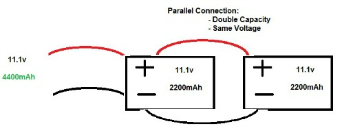
As can be seen from the above diagrams, connecting in series or parallel has a different effect on the characteristic of the battery. Sometimes, you may see shorthand used, such as 12s4p, which denotes 12 cells in series, and 4 cells in parallel. When connecting cells to build a battery, it is important to remember the basic rules of circuitry:

  1. Don’t cross (connect) the positive and negative of a cell, or of the battery pack.
  2. In order to connect cells in series, they must be similar in capacity, or be of identical parallel count.
  3. Know your system’s capabilities in order to not exceed the specification of any one given part.

Now it is the third rule that leads us to our next point. Irregardless of the form factor, each cell has its own specifications and capabilities, and it is important that these are understood to ensure a safe battery.

For example, the aforementioned 30q is rated for 3000mAh (milli-amp hours) and at 15 Amps maximum discharge. If these specifications are exceeded, you may cause damage to the cell (possibly irreparable), or even cause a complete failure. Now, the details of this are semi-complicated, so let’s look at each of the aspects individually.

  1. Capacity- The capacity of a cell is normally rated in mAh. Like any scientific unit, if the capacity is large enough, it may also be written as Ah with any prefix. Now many of us are used to seeing capacity rated on a 1-100 percentage scale. However, that’s not actually how it works behind-the-scenes. Continuing to use the 30q’s as an example, the maximum voltage per cell is 4.2v. This is equivalent to 100% state of charge. 2.8 - 3v is the minimum cell voltage, this is equivalent to 0% state of charge. Anything below this is dangerous to you and the cell. Cautionary tales are told of those who have successfully revived cells from these lower voltages, but as a beginner, I would urge you to stay away from taking such risks. The range between 4.2v and 2.8v is about 3000 mAh for the 30q. The higher the mAh rating, the more capacity you have.

  2. Discharge- The Amp rating (or C rating for LiPo’s) details how many amps can be drawn from a cell. First, it’s important to understand the relationship between current and heat. The higher the current, the higher the heat. When discharging cells closer to their maximum rated discharge, they are likely to begin to heat up. The increased heat will limit current draw, and if the temperature becomes excessive, can become problematic. Furthermore, heat energy is wasted energy, so keeping your packs cool is important for efficiency and safety.

Here is where the line blurs a little. With certain cells, you can safely discharge them at higher amps than what they are rated for, given that they stay cool. The 30q is one of these cells. Although rated for a max of 15A discharge per cell, many have found that they are safe for a 20A discharge. This is not a behavior present in all cells, and it is at your own risk, so please conduct appropriate research prior to attempting to push your cells over what they are rated.

A trusted source for cell specs is @Battery_Mooch, who tests a variety of cells himself, and gives realistic ratings for cells. Sometimes the manufacturer’s specification sheet is inaccurate (over or under rated), when choosing cells conduct thorough research as to what they are capable of, and if they are suitable for your intended use.

14 Likes

Nice write up!

I‘d like to add a bit a context to the „C-rating“ which is mainly used for lipos.

The general thought is, that with the C-rating you can calculate the continues discharge current of the pack by simply multiplying the C-rating with the capacity of the cell (in Ah).

So a 5Ah cell with a C-rating of 60 would be able to output 300A for a full discharge cycle.

The reality is, that C-rating doesn’t have any standards.
That means every manufacturer could define 1C in his own way.
Let’s take the 5Ah 60C pack as example.
The pack could output 300A for a full discharge, but would the welding taps or the 12-10AWG wires or plugs withstand that current for a full discharge cycle?

C-rating on lipos is often used for marketing purposes, but fortunately it’s not all that bad.

If you buy quality packs from legit sources you can go with the rule of thumb that at same capacity the packs with higher C rating will have less voltage sag, run cooler and with it as well last longer than one with a lower C rating.
If you take 50% of the theoretical cont. discharge current (C* cell Capacity) you will get a way more realistic current value at which you can discharge the cells.

Disclaimer: There are always exceptions, but exceptions prove the rules :joy:

8 Likes

Nicely done!
I would just toss in that “empty” for a Li-ion cell, or 0% charge, is 2.5V for almost any cell we would use. There are a couple that are rated down to 2.75V and a couple that are rated 2.0V but I’ve never seen them used by anyone.

No extra damage will occur when going down to this 2.5V rating as the cycle life of the cell is determined by discharging down to that level (and up to 4.20V). The cell is designed to be discharged to 2.5V every time and that is the voltage used to determine the capacity (mAh) rating of the cell.

Staying a bit above that, perhaps 3.0V or even higher, can help slow down the aging of the battery a little bit and extend its overall life but is not necessary from a safety point of view.

Stopping early, at 3.0V per cell, means that the running time of the battery pack is shortened a bit (since you are not discharging each cell down to empty) but not by much.

5 Likes

@Battery_Mooch at which voltage LiIon cells usually start to take serious damage?
Lets say we set our esc cut off voltage at 2.5V per cell and are cruising right now at around 2.6V per cell just the last bit to make it home…but there is this last hill we need to manage… We accelerate and baam the voltage drops down to 2-2.2V because our esc isn’t fast enough to cut off at exactly 2.5V.
Sure our board is now without power and the voltage might go back up to 2.4-2.5V, but what would this mean to the health of the cell?
I always thought that 2.5V is the absolute absolute borderline. Below that and the cell is fucked.
If that’s not the case I‘m happy to change my cut off limits on all my boards for that bit of extra range :joy:

5 Likes

Damage occurs 24/7 even just sitting around, “calendar aging” it’s called. A lot depends on what you consider to be damage and the type and magnitude of it.

Serious and obvious damage after one exposure to a low voltage? Might not happen at all even down to a fraction of a volt if you recharge right away very slowly. It depends on the cell though, I can’t say every cell would have no problems every time being overdischarged and recharged quickly.

But the 2.5V rating is the voltage limit if you want to have the rated cycle life of the battery. The lower in voltage you drop to the more the cycle life gets zapped.

Then your battery was never below 2.4V-2.5V. :grin:
The voltage it sags to when being used is an “illusion” caused by the internal resistance of the battery and unequal distribution of the ions. When the current stops you don’t have that voltage drop affecting things and the ions can redistribute equally around the cell. This is the cell’s true voltage, its “resting voltage”.

If it rises back up to 2.5V then you are staying within its ratings, assuming you never got crazy low and the cell didn’t get too warm inside, and only normal aging is occurring.

But the internal resistance can go way up at these lower voltages (heating up your pack) so make sure your cells aren’t getting more than a bit warm if you lower your cutoff voltage.

Nope. It’s just the voltage to not go below to get the rated cycle life.
But going below about 2.0V for some cells, I don’t have a list, can cause the copper (negative) electrode to literally start dissolving. When you recharge that cell that dissolved copper starts plating out all over the place and that can eventually cause loss of capacity and even an internal short circuit…which is universally considered to be a bad thing.

IMO, setting a cutoff below about 2.8V/cell gets you almost nothing in terms of extra run time and just heats up the cell. There’s just no capacity (charge) left in the cell at much below about 3.0V.

6 Likes

I was sold the same bill of goods. Imagine how many usable batteries have been tossed due to this misinformation.

3 Likes

Ok, noobish question. Used cells? Obviously not ideal but some possible good deals seem to be around…?
Batteries cost heaps living on a small island in the pacific so interested in possible other options.

Capacity test - want to retain close to original and closely matched. Some sellers advertise this info.

I have heard internal resistance matching is important but how is that tested? Worked out?

Anything else?

No burning desire to buy second hand cells, really, but a couple of deals on local auction sites which seem too good to be true (alarm bells…?)

Eg. 100used P26a for $220NZD (around $150 freedom bux)

1 Like

I know @Radium just did an IR matched battery, perhaps Liam or @Battery_Mooch can shed some light on hardware required for resistance testing?

1 Like

It depends on whether you want to measure AC or DC internal resistance. DC internal resistance better tracks how much the cell will sag when actually used so I typically recommend that if matching cells for a pack.

If you want to measure AC IR a very accurate meter, also easy to use and affordable, is the YR-1030 on AliExpress from several vendors.

Forget using the DC IR testing feature of most round cell chargers…uselessly inaccurate. The SkyRC MC3000 can be okay if you press against the bottom contact while measuring and take several measurements, removing and rotating the cell each time, and averaging the readings.

The better hobby LiPo chargers, iCharger and Turnigy and others, can be very accurate but you must calibrate out the resistance of your wires, connections, and the test jig you build to hold the cell.

The ESR meter available at www.progressiverc.com is fantastic for DC IR testing, been using them for years, but might be too expensive unless you’re building lots of packs.

You can get a rough idea of DC IR by just pulsing the cell with resistors at two known current levels, measuring the voltages, and the using Ohm’s Law to get the equivalent resistance. Probably not accurate enough for cell matching though without a lot of attention paid to consistency.

All testing must be at the same charge level and same internal cell temperature. I recommend fully charging each cell in the same charger slot, waiting at least 1/2 hour (same amount each time though), and testing the IR with a minimum of handling. All at roughly the same ambient temperature.

The crazier you get with all this the better the performance of your pack will be. But the return on your time and $$ spent can get very small very quickly. It’s probably not worth weeks of your time and hundreds of dollars for a pack that runs 1% longer. Each of us has to decide how far to go and what our priorities are.

7 Likes

Exactly the kind of elaborate and well executed answer that is surely appreciated. Thanks Mooch!

5 Likes

Cheers @Battery_Mooch, great info!!
Not embarking on that just yet :joy:

5 Likes

I don’t think my first attempt at measuring each cells IR resistance and evenly distributing across each P group worked so well. It was actually a little less balanced than other packs I’ve made with P42A cells in the same P configuration, oddly…

What I intend on trying next is capacity matching (although tedious). Using li-ion chargers to capacity test every cell and then distribute them based on capacity rather than IR, in hope that this would be a better way to keep the pack balanced.

I’m not really sure yet what is the best way (if any) to tell how the cells capacity will change over time as it degrades, as cells in a pack all seem to degrade at their own rate

3 Likes

Both capacity and DC IR are important.
The IR determines how far the cell’s voltage sags as soon as the discharge starts. The capacity determines how quickly the cell’s voltage continues to drop as the discharge continues. Both of those determine how long each cell will run before the cutoff voltage is reached.

Matching both IR and capacity is the best way to start with a fairly well matched pack. But cells age differently depending on their location in the pack. Temperature differences through the pack and small cell-to-cell differences force the cells to age differently. Add this on top of the small differences in IR and capacity even with well matched cells and you will still end up with a pack that eventually has unbalanced cells. This is where the BMS comes in. :slightly_smiling_face:

Each cell will indeed age at an ever so slightly different rate.

How quickly the capacity fades overall depends on the model of cell and how hard they are used. Under a bit of abuse I often see about a 2mAh loss per complete 4.2V-2.5V-4.2V cycle for the first 50 cycles or so then about a 1mAh loss per complete cycle after that.

But gentler use could mean a much smaller per-cycle loss and rougher use could mean a much greater per-cycle loss. A warmer cell from the middle of the pack could lose capacity faster than a cooler cell on the outside of the pack.

IR doesn’t change much over the life of the cell, compared to capacity, unless badly damaged.

6 Likes

This is great info. Thanks Mooch!!
So have taken the plunge on a bunch of used P26a cells, all capacity tested by seller, all above 2600mAh still and marked on cells. 100cells (10s10p maybe)

Will see how it turns out. :joy:

4 Likes