Whats up you cool cats and kittens. The Robot is busy, so I robbed him blind and took over his build guide plans. The duck’s in charge now.
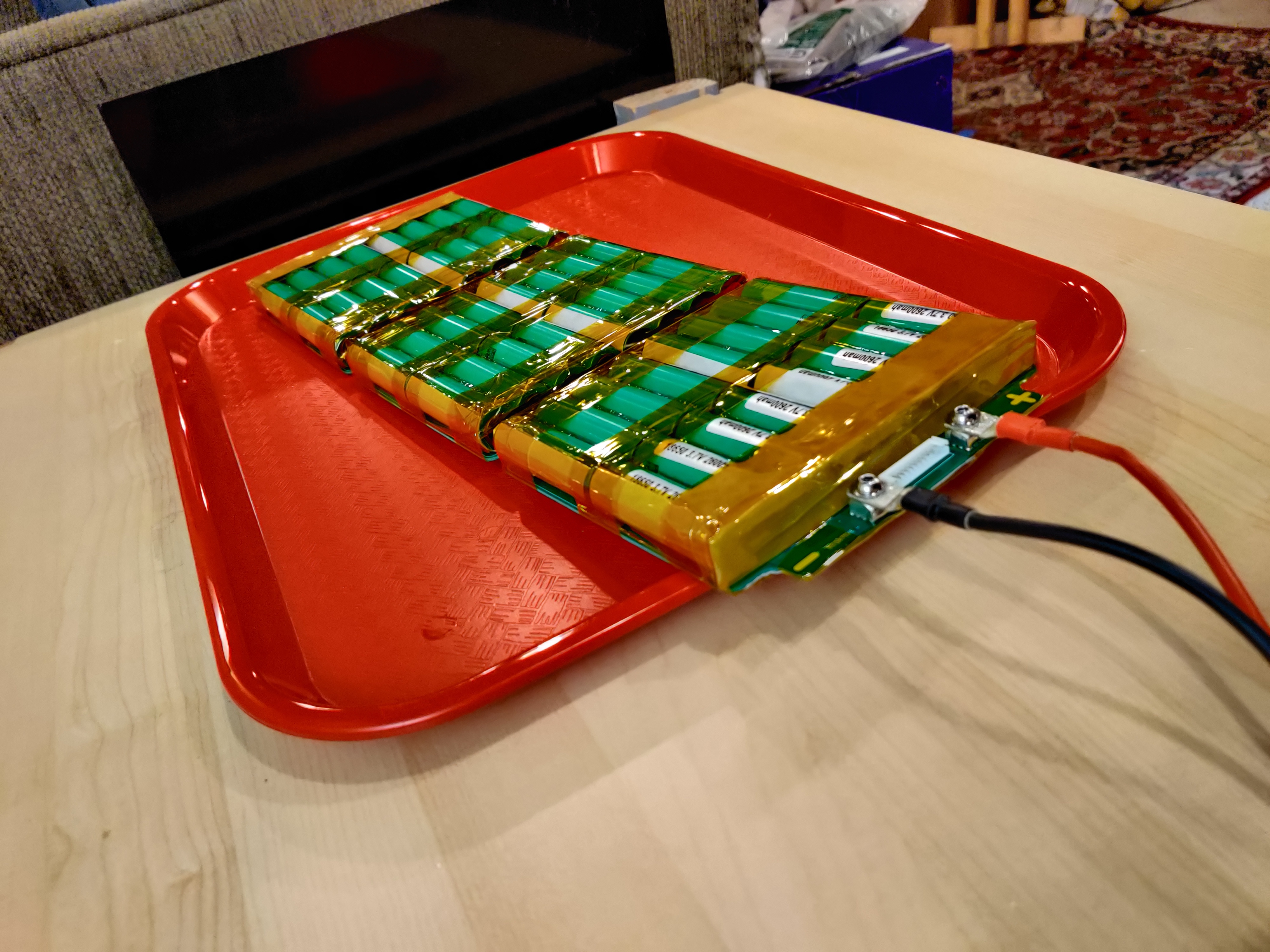
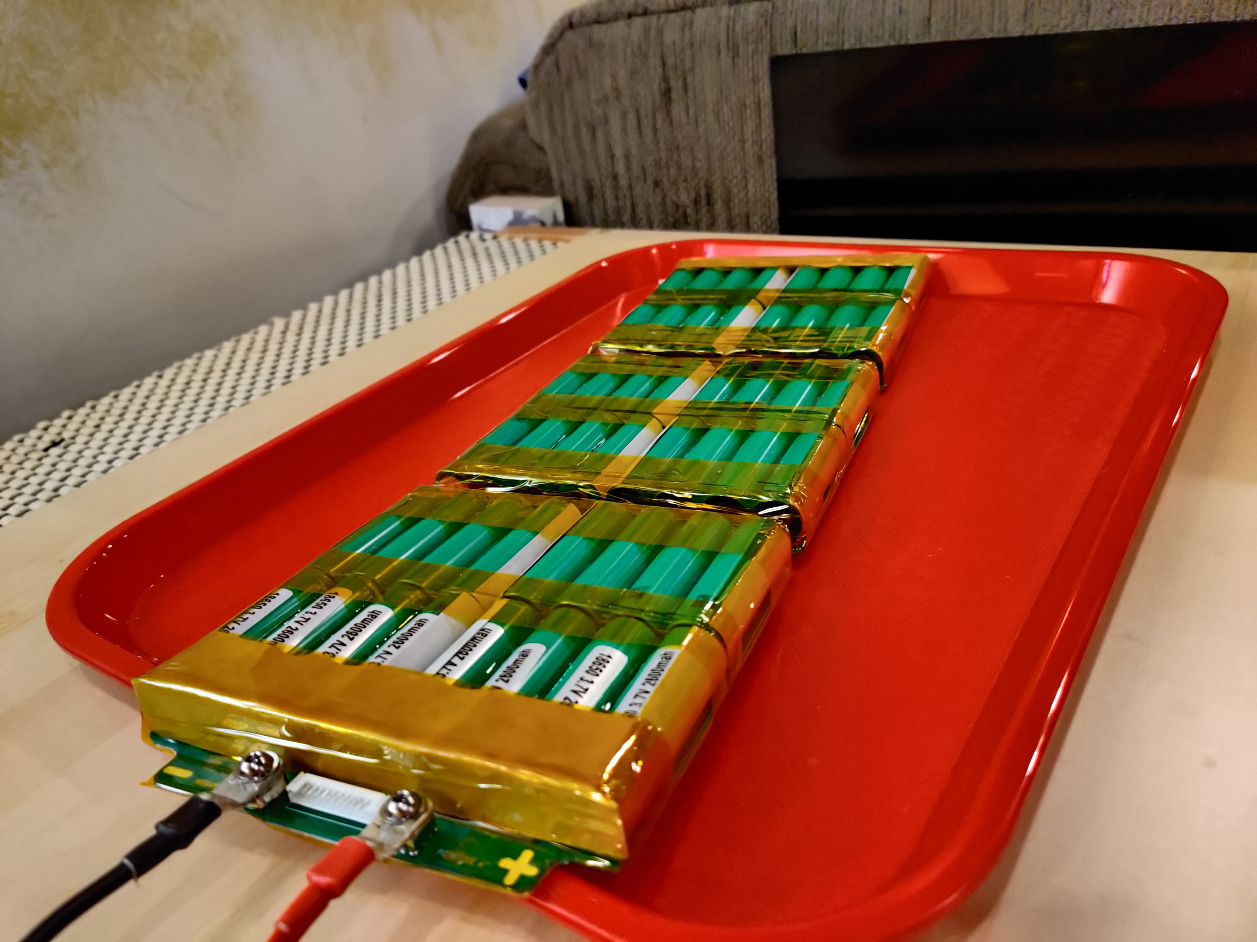
Today we are going to learn about building a “DRI 12S4P FlexPCB Battery Kit!” This thing is as simple as it gets, so even a bunch of knuckle-draggers like yourselves should be able to do it, provided that you have the necessary materials and equipment. Here is what we are making:
Build time  (including prep work): 6 hours and 32 minutes
Materials and Equipment: 🛠️
Materials:
- 1x DRI 12S4P FlexPCB Battery Kit
- 48x 18650 cells of your choosing. Popular choices are Samsung 30Q, LG HG2, Sony VTC6, and many more. If you are purchasing cells, its a good idea to get a couple extras in case any show up dead or test different than the others.
- Neutral-cure silicone
- 48x Fish paper rings
- Fish paper. Self adhesive to make your life easier.
- Kapton Tape
- Solder (I recommend 60/40 leaded flux core solder, but use what you like.)
- 2x m5*10mm button head or socket cap bolts
- 12AWG to 8AWG copper cable
- 1x Female XT90S plug
- Heat shrink
Equipment:
- Spot welder
- Soldering iron (bigger is better to push a lot of heat quickly)
- Tin snips or sheet metal scissors
- Wire strippers
- Multimeter
- Hot glue gun
- 18650 glue guide (I remixed @Lee_Wright’s glue guide as his was just a tad too small.)
Procedure:
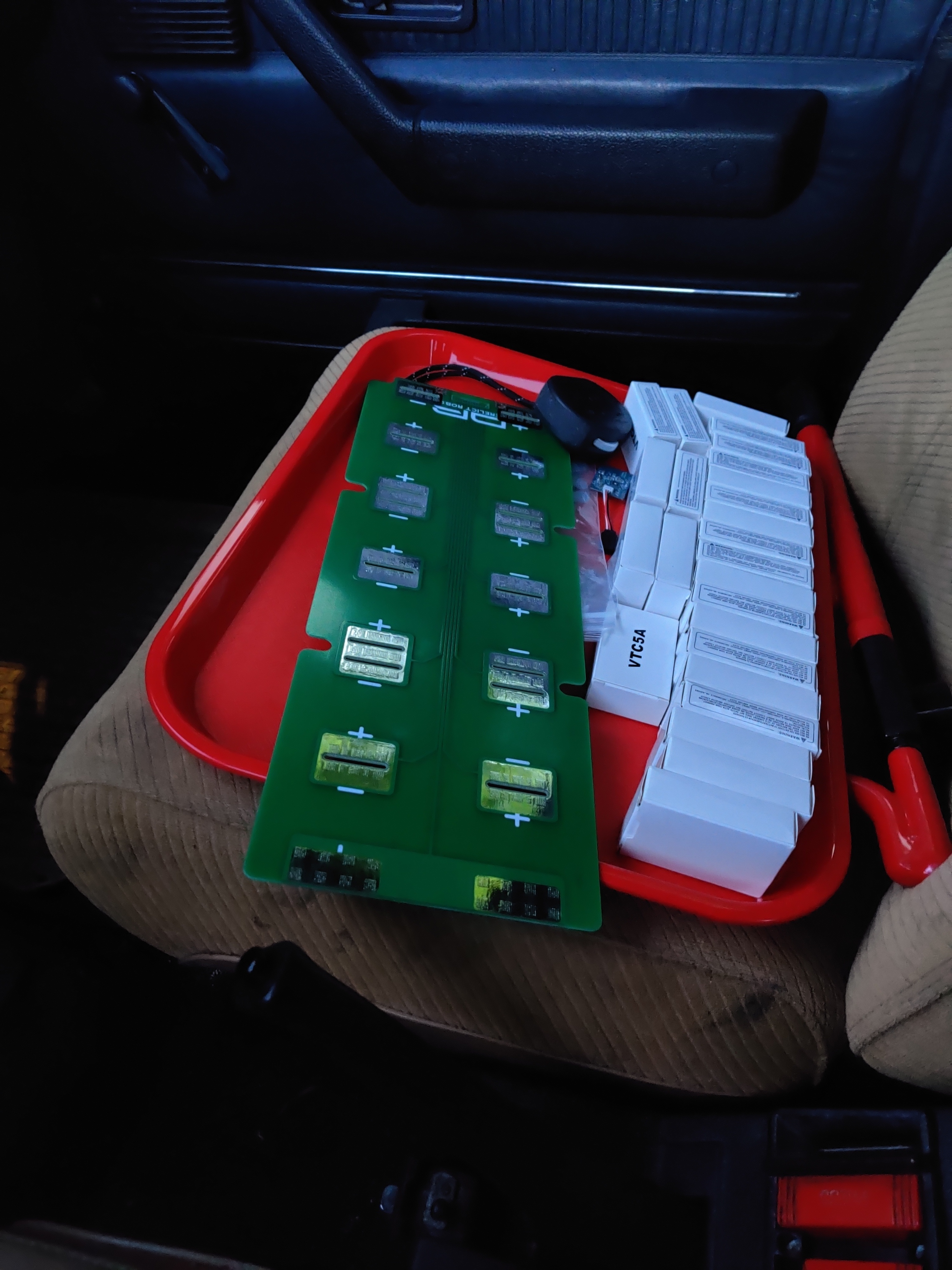
Step 1: Prep ✅
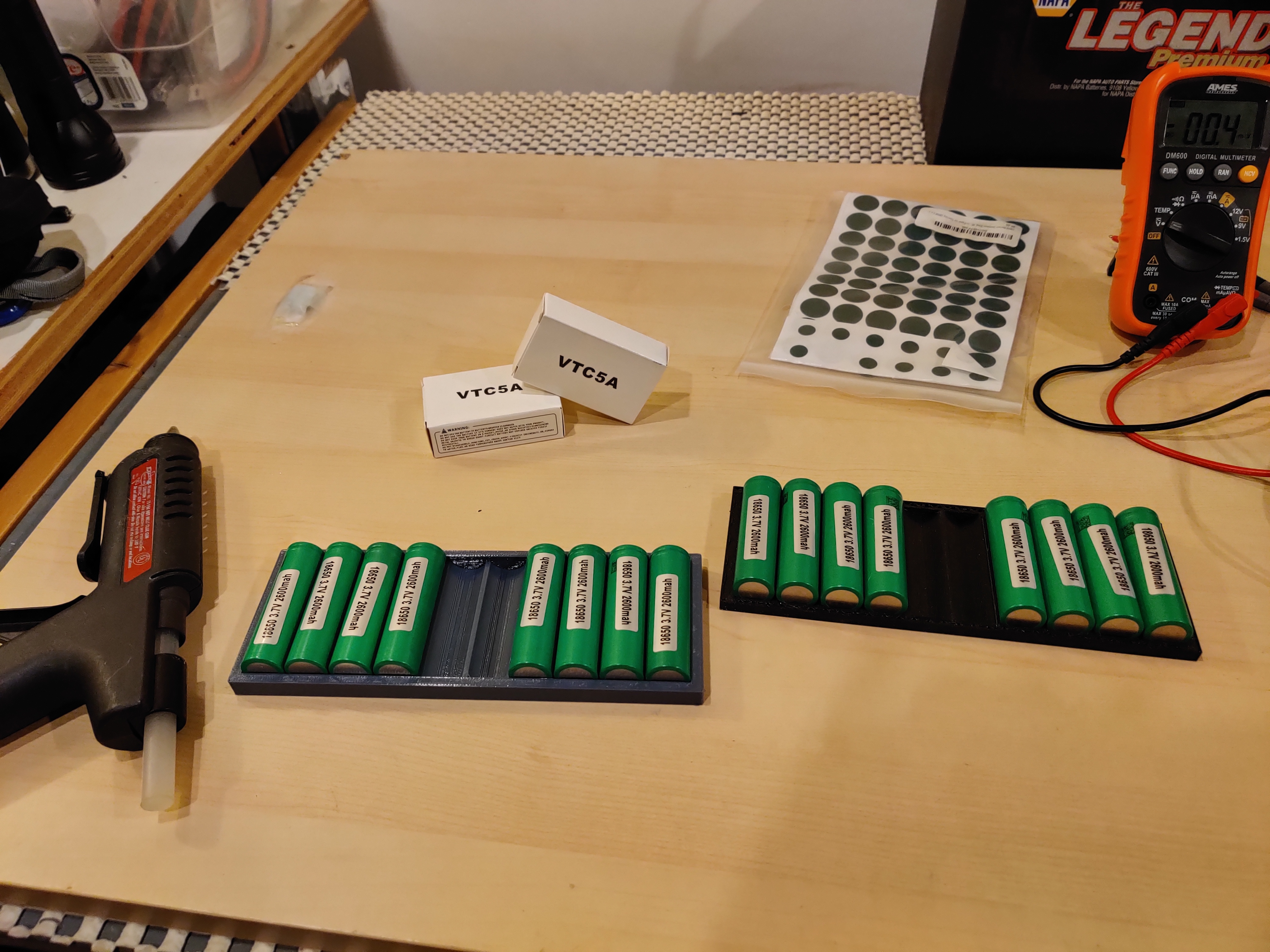
Test each cell with the multimeter first to make sure they are all within +/-0.05v of each other (or as close as you feel comfortable with). Pretty much just pull any cells that are much lower than the others, and replace it with one of your extra cells. You took my advice and bought extras, right? Good.
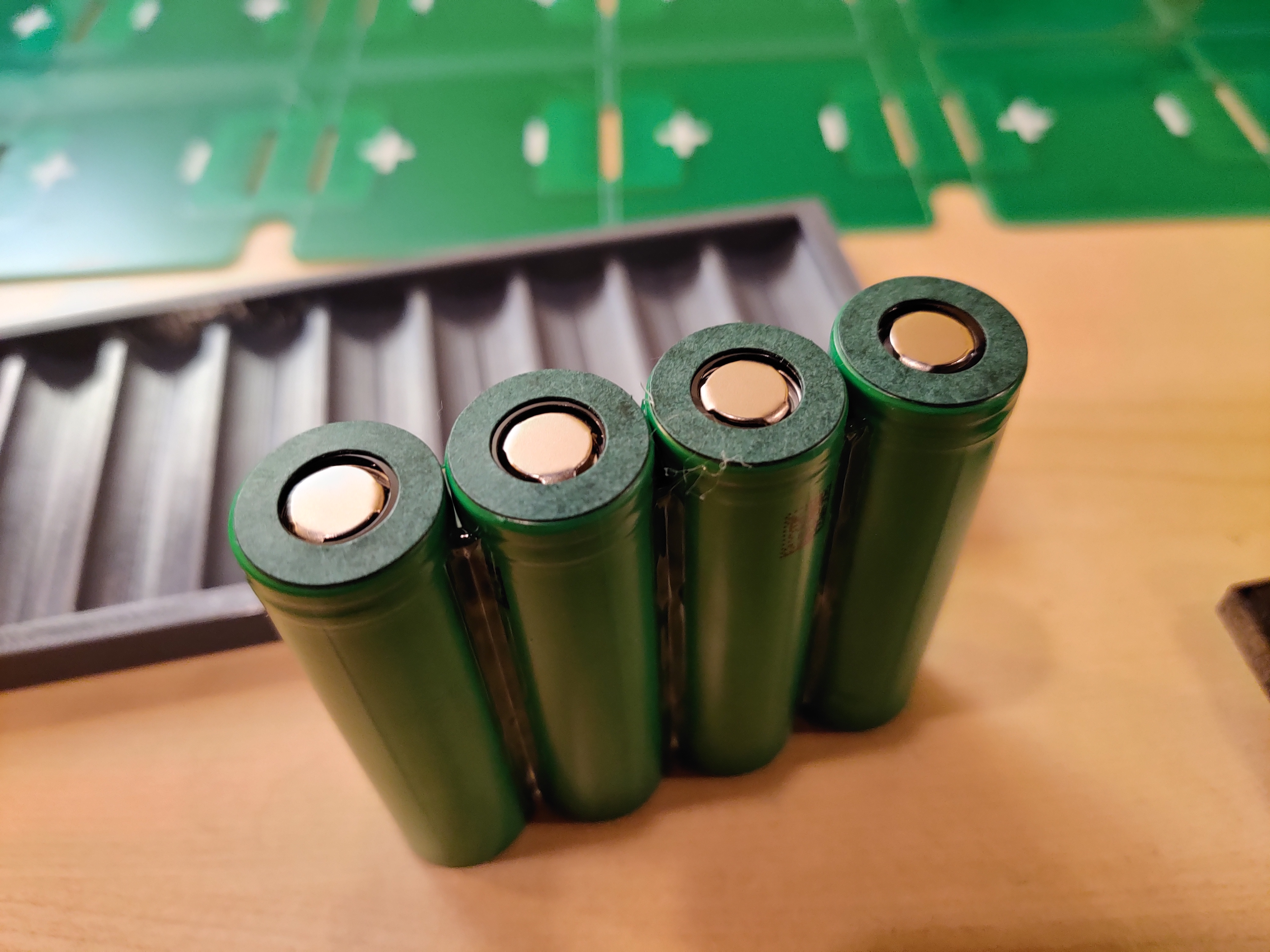
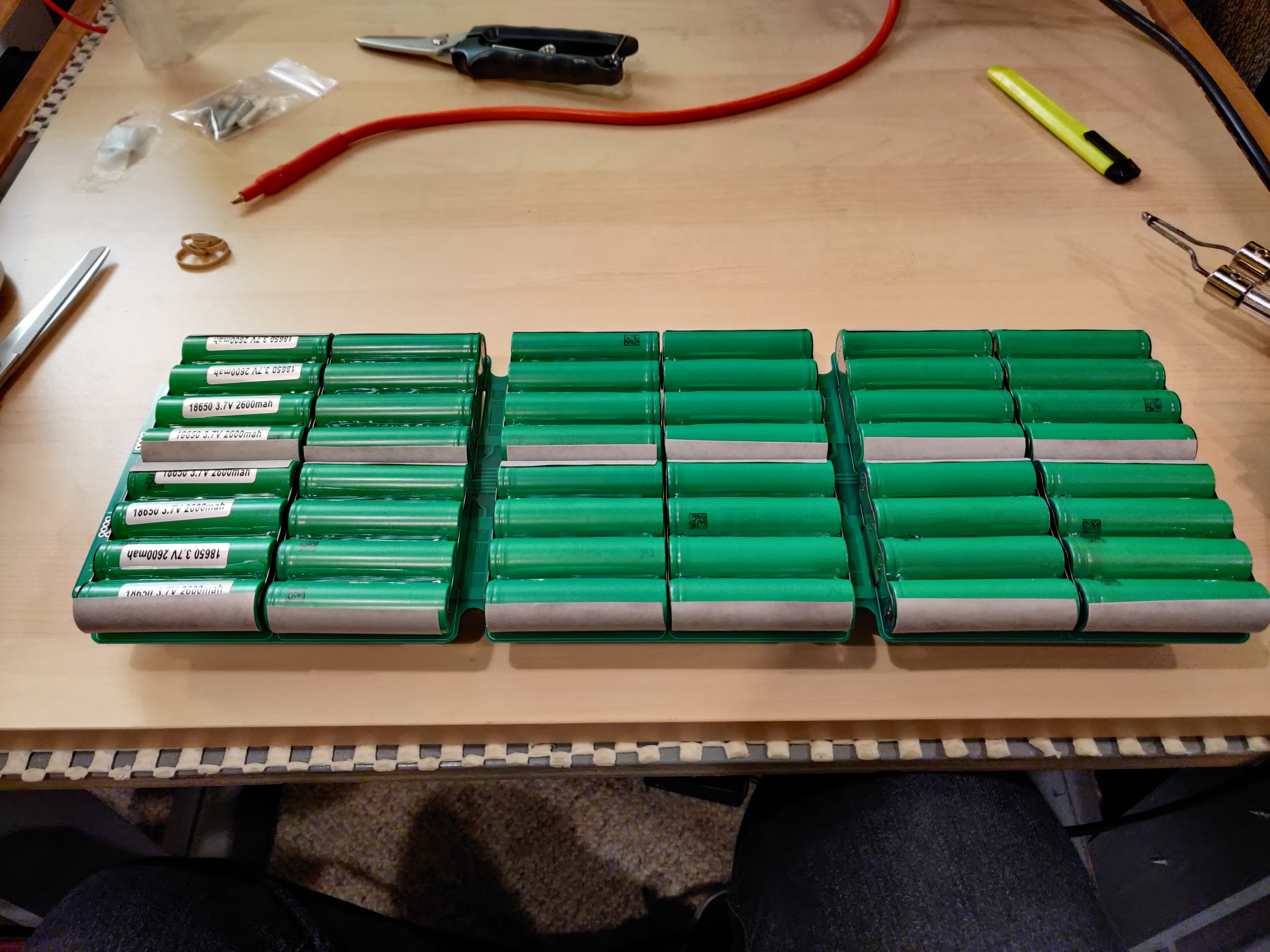
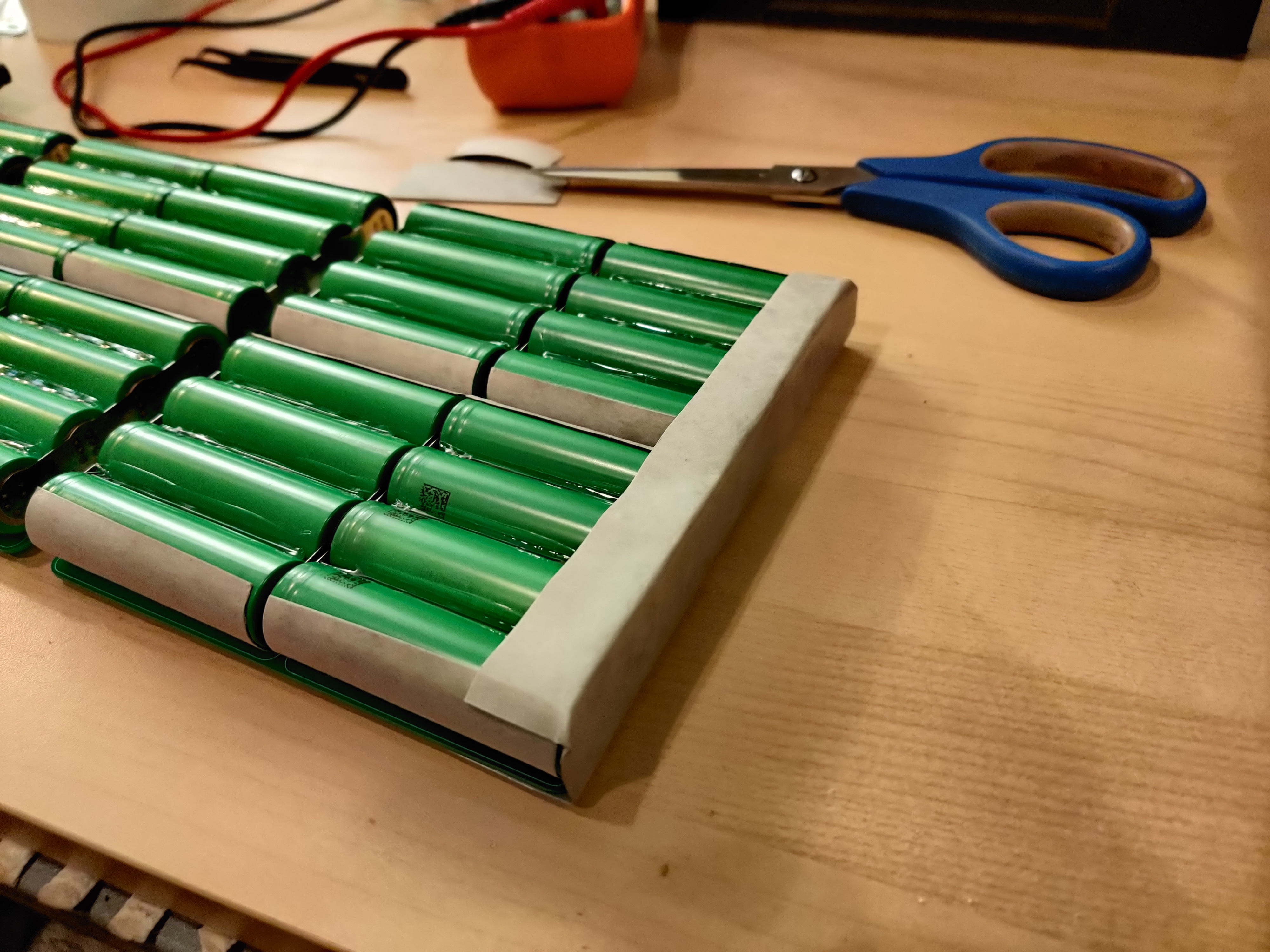
Now hot glue or silicone your cells together into groups of 4. This is also a great time to insulate the positive terminals with fish paper rings. Make sure you get the rings centered so they cover the shoulder of the cell all the way around.
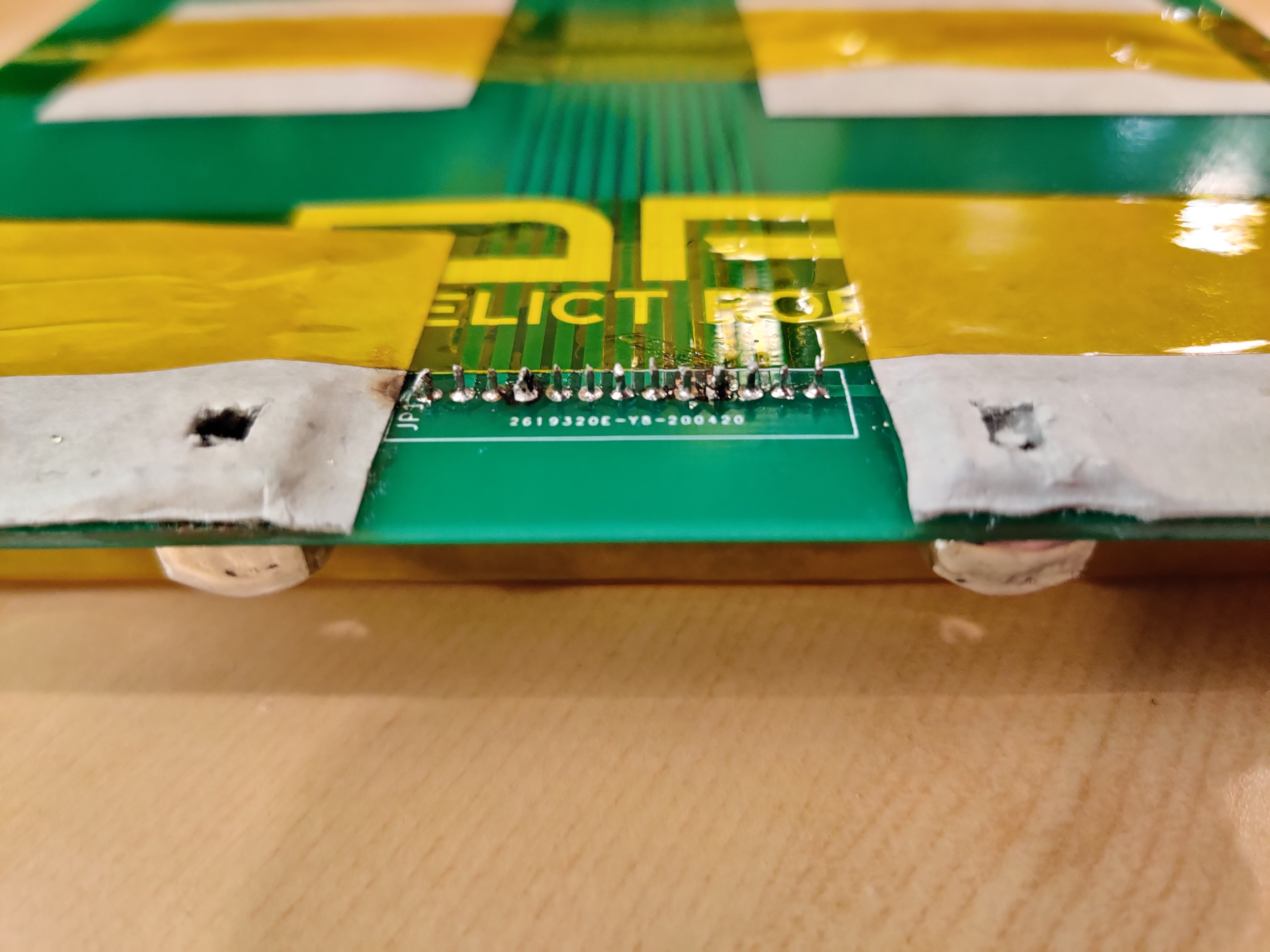
You’re also going to want to solder on the balance plug (or your BMS’s wiring harness) at this point. Definitely dont forget this and then do it later when all the cells are welded and soldered in place. That would be bad and dumb.
Step 2: Spot weld 💥
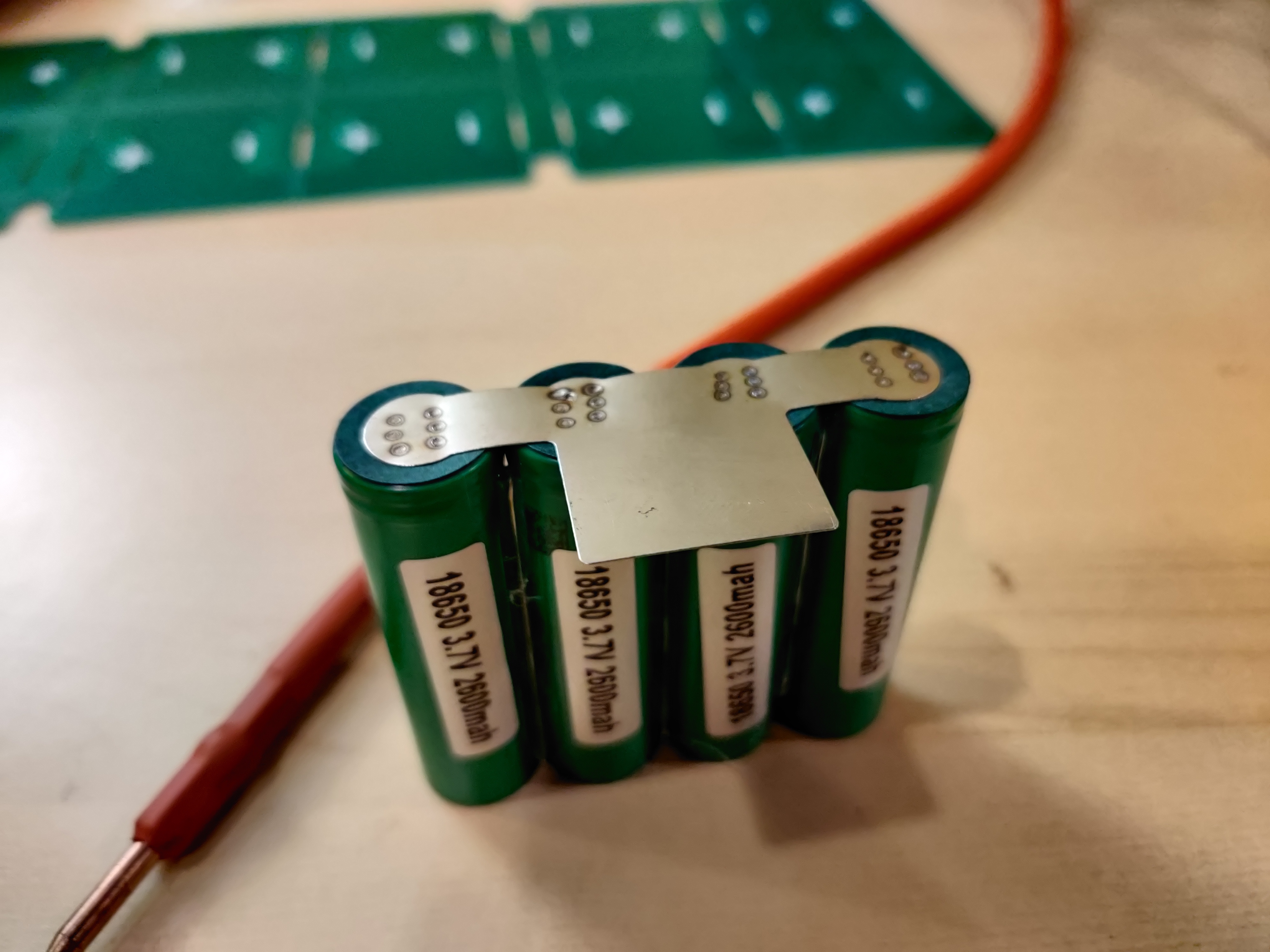
I used some little magnets to hold down the nickel tabs while I did my first welds.
These tabs are 0.2mm thick, so if you are used to welding 0.1mm or 0.15mm, you will have to turn that shit up, yo. You know your welder better than I do, so just make sure you’ve got good welds.
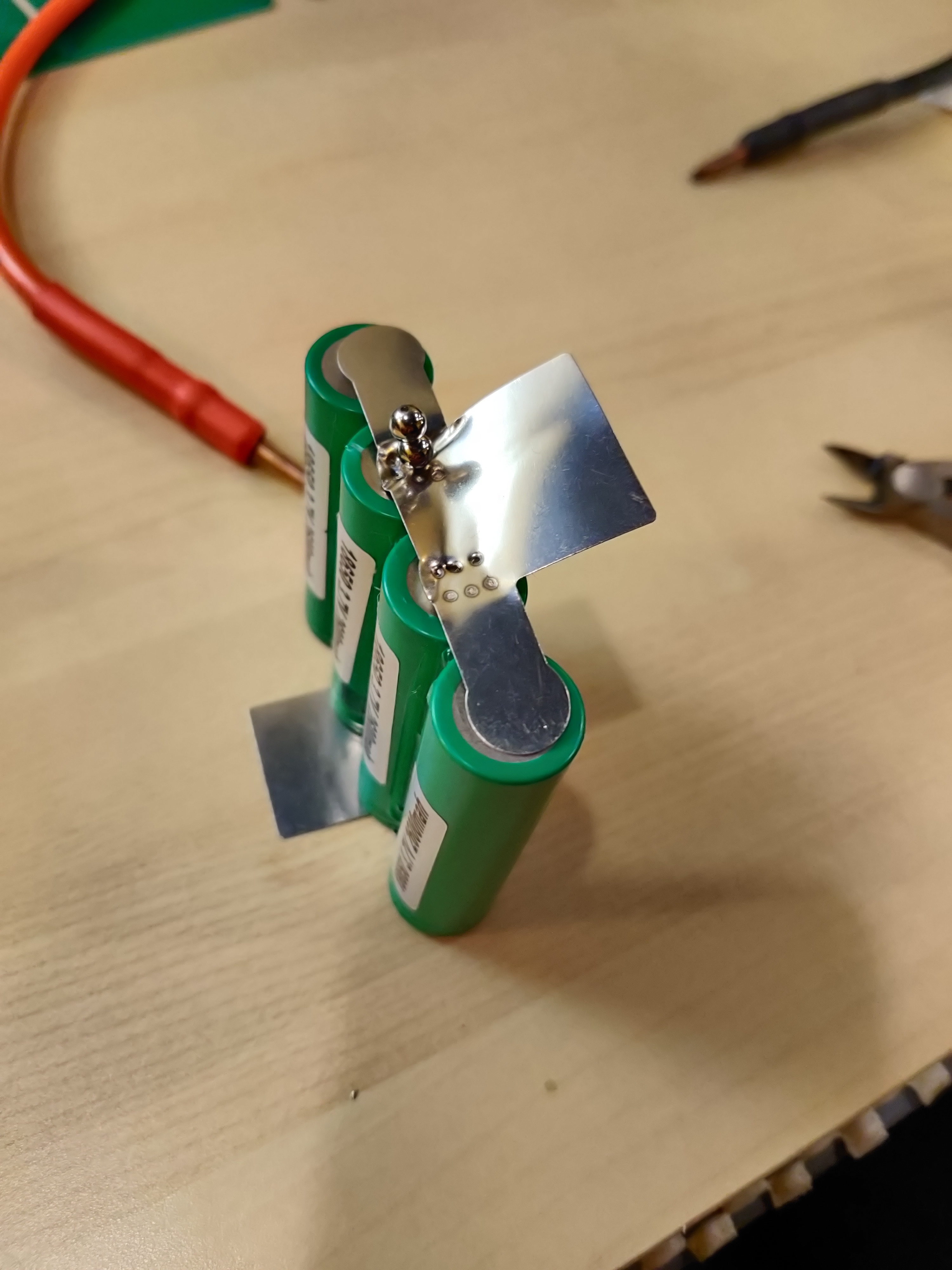
Also make sure you dont accidentally weld a tab backwards, because ripping it off will probably ruin it (assuming your welds are decent).
Step 3: Splooge 💦
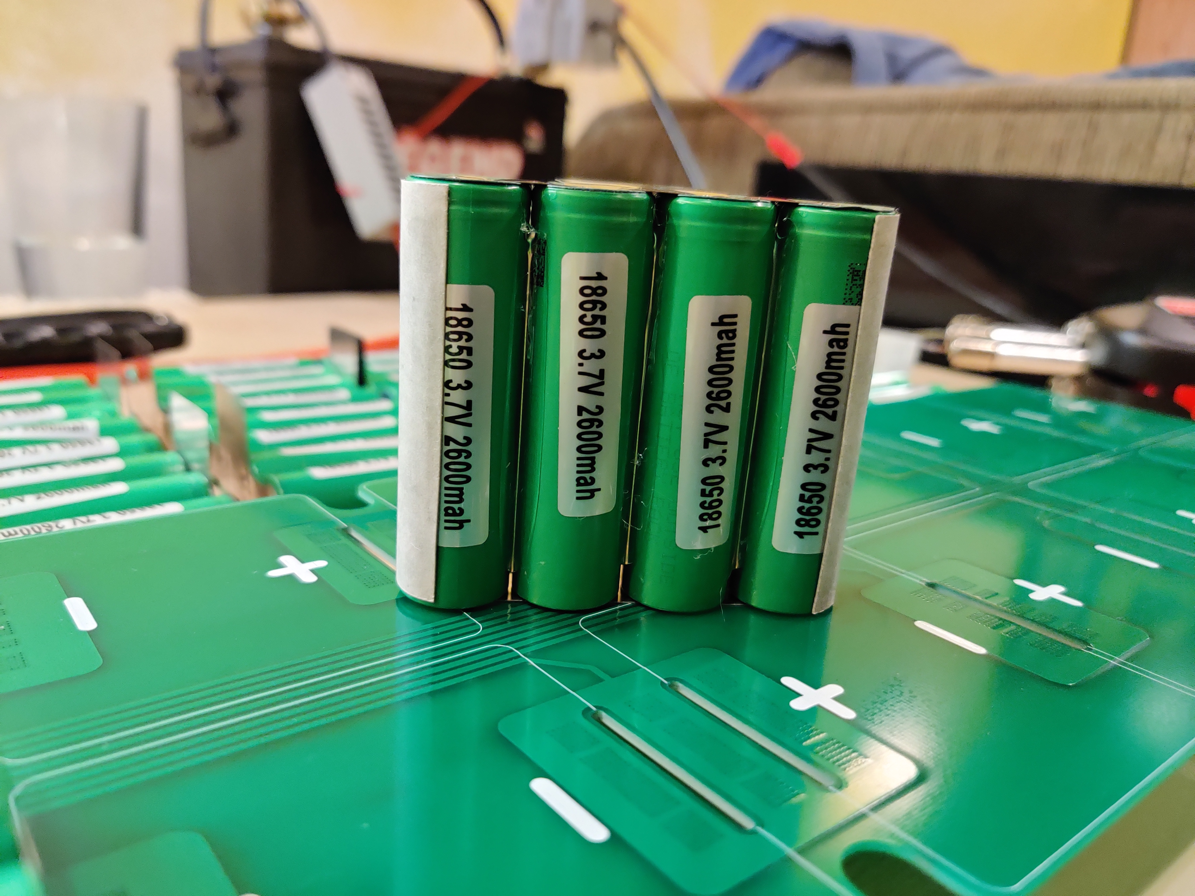
Fish paper the sides (or more) of each welded p-pack to protect from shorts.
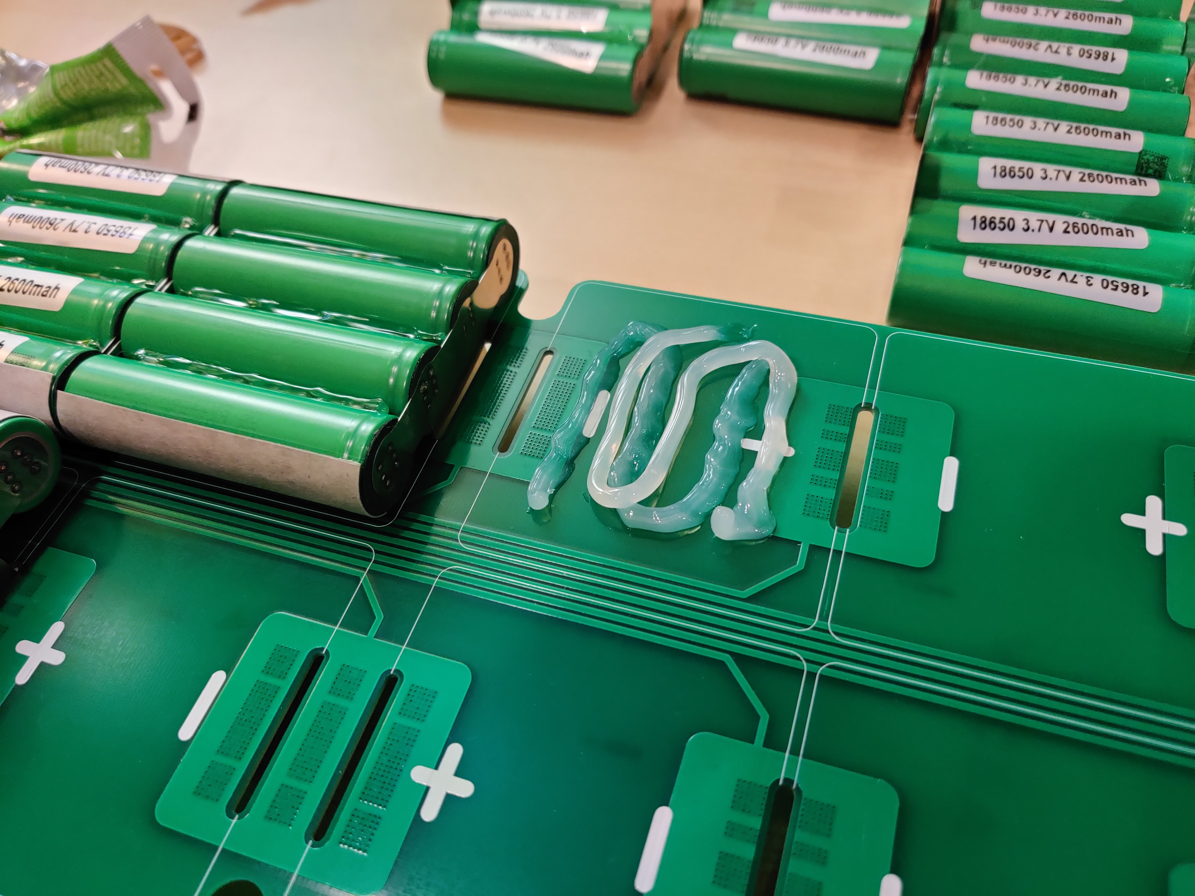
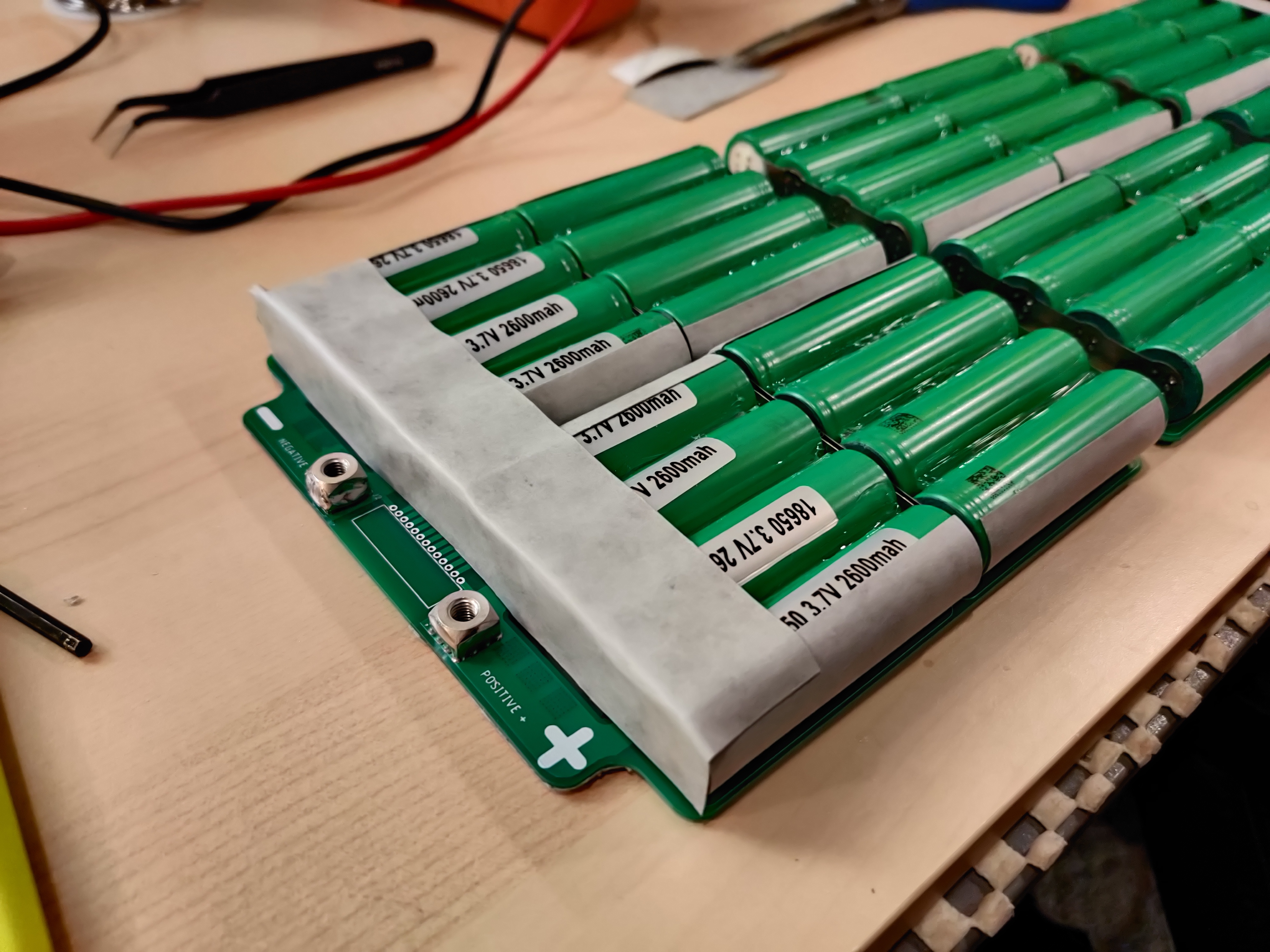
Splooge a bunch of neutral cure silicone onto the PCB and stick each p-pack down.
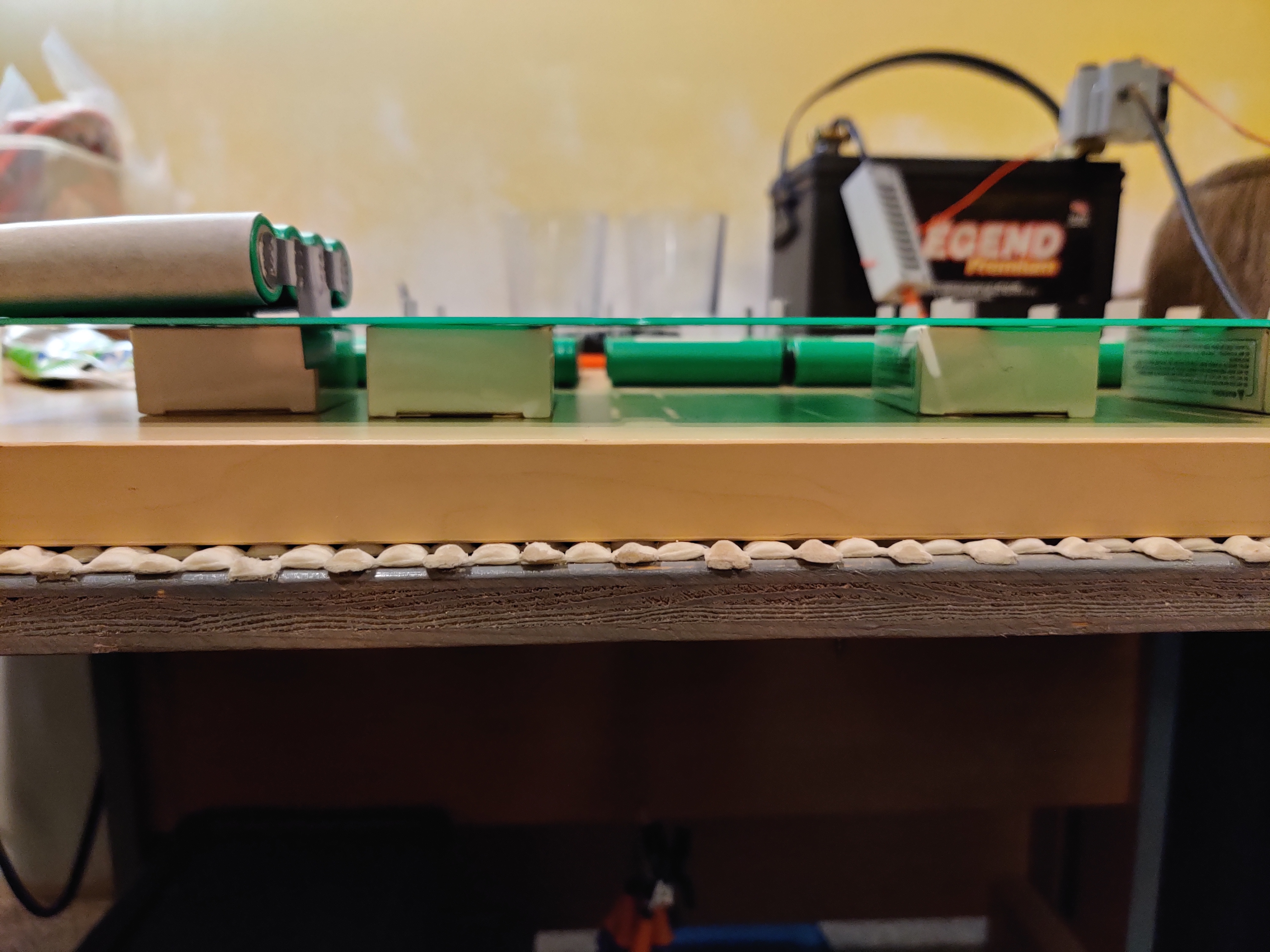
You will have to insert the tabs through the slots at this point, so it may help to have the PCB propped up with something (I used the empty boxes my cells came in). Make sure you are lining the p-packs up with the positive and negative markings printed on the PCB.
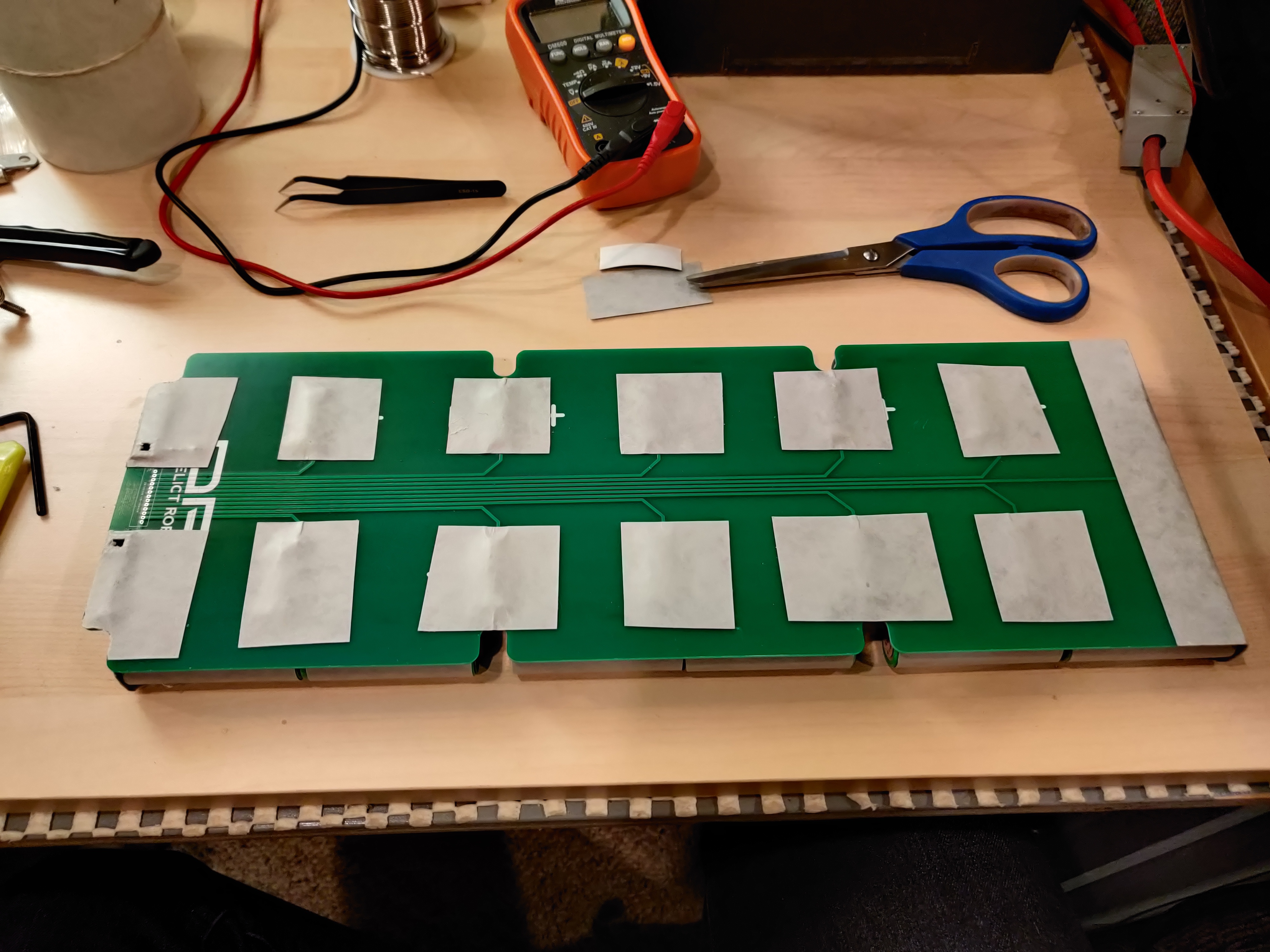
Once this is all done and you flip the pack over for step 4, you should probably cover all your exposed terminals with painters tape or whatever to avoid shorts.
Step 4: Spot welding pt.2 💥💨
Your spot welder power should be much lower when welding nickel to PCB than when welding nickel to cells
At this point it is also probably good to bring up that the copper pours on this PCB should never be carrying the full series current of your pack on their own. Therefore the spot welds we are doing here is just to stick everything together before we beef up the connections in the next step.
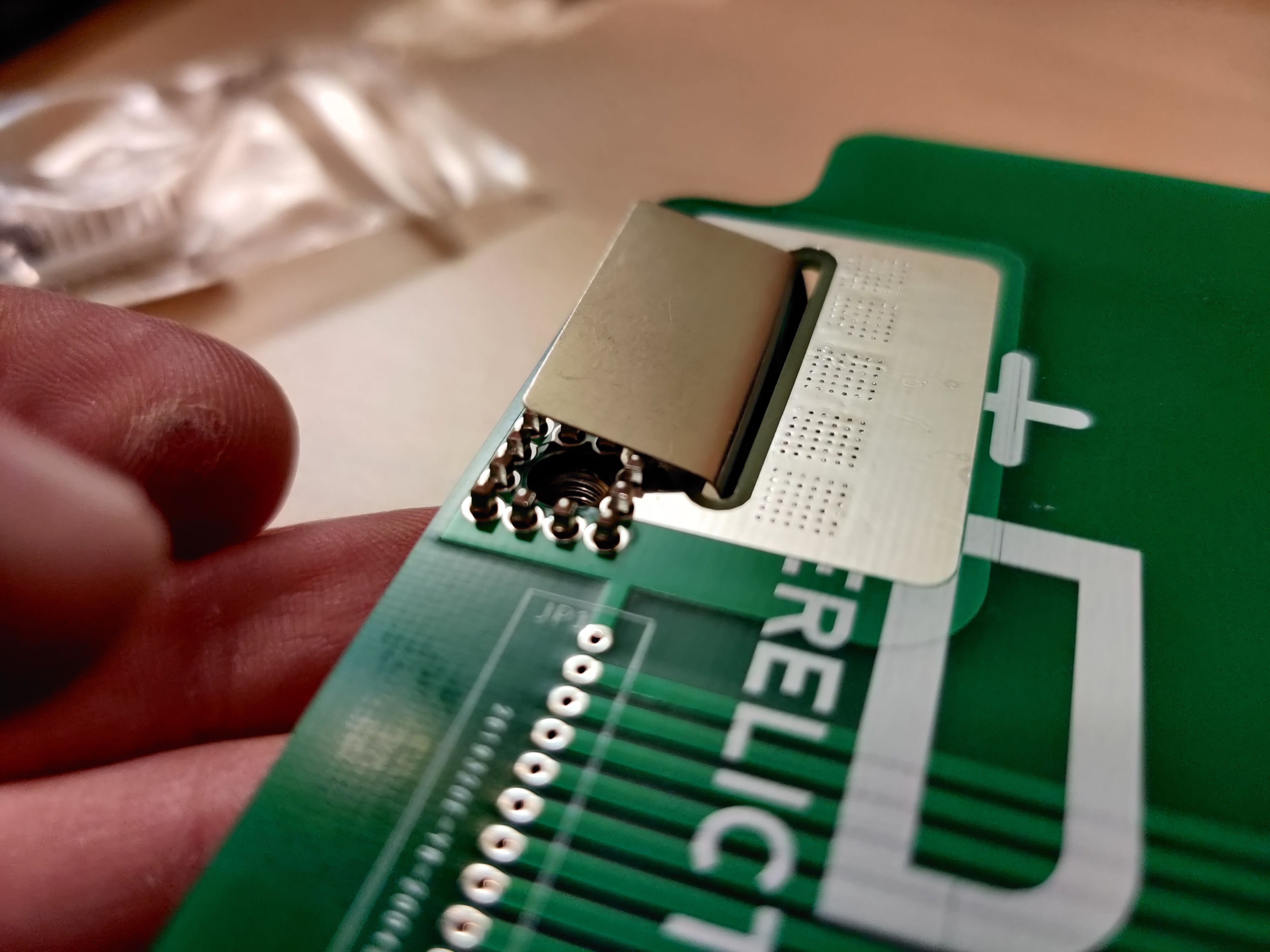
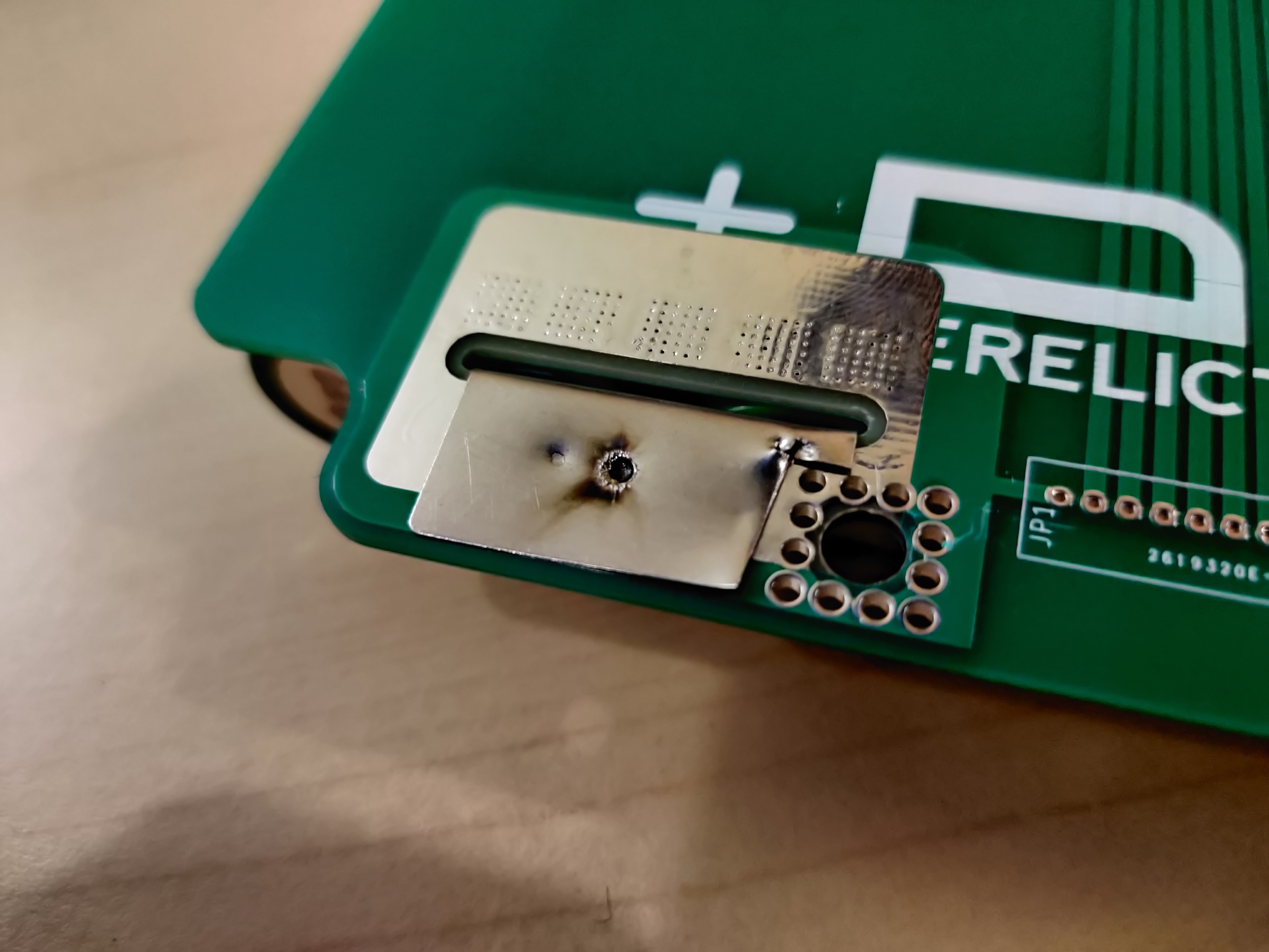
The footprint of the bush terminal encroaches a bit on the nickel, so trim that away.
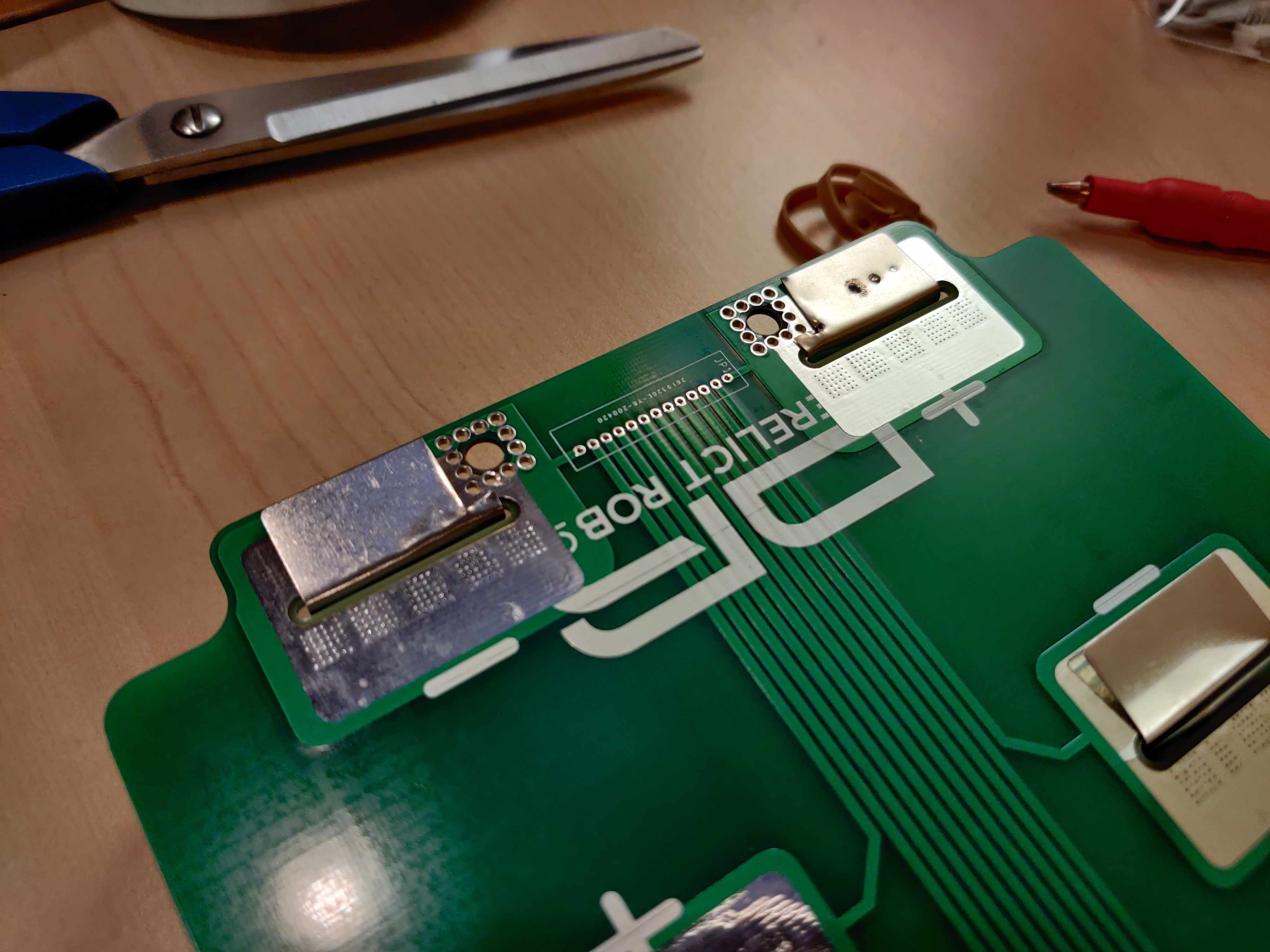
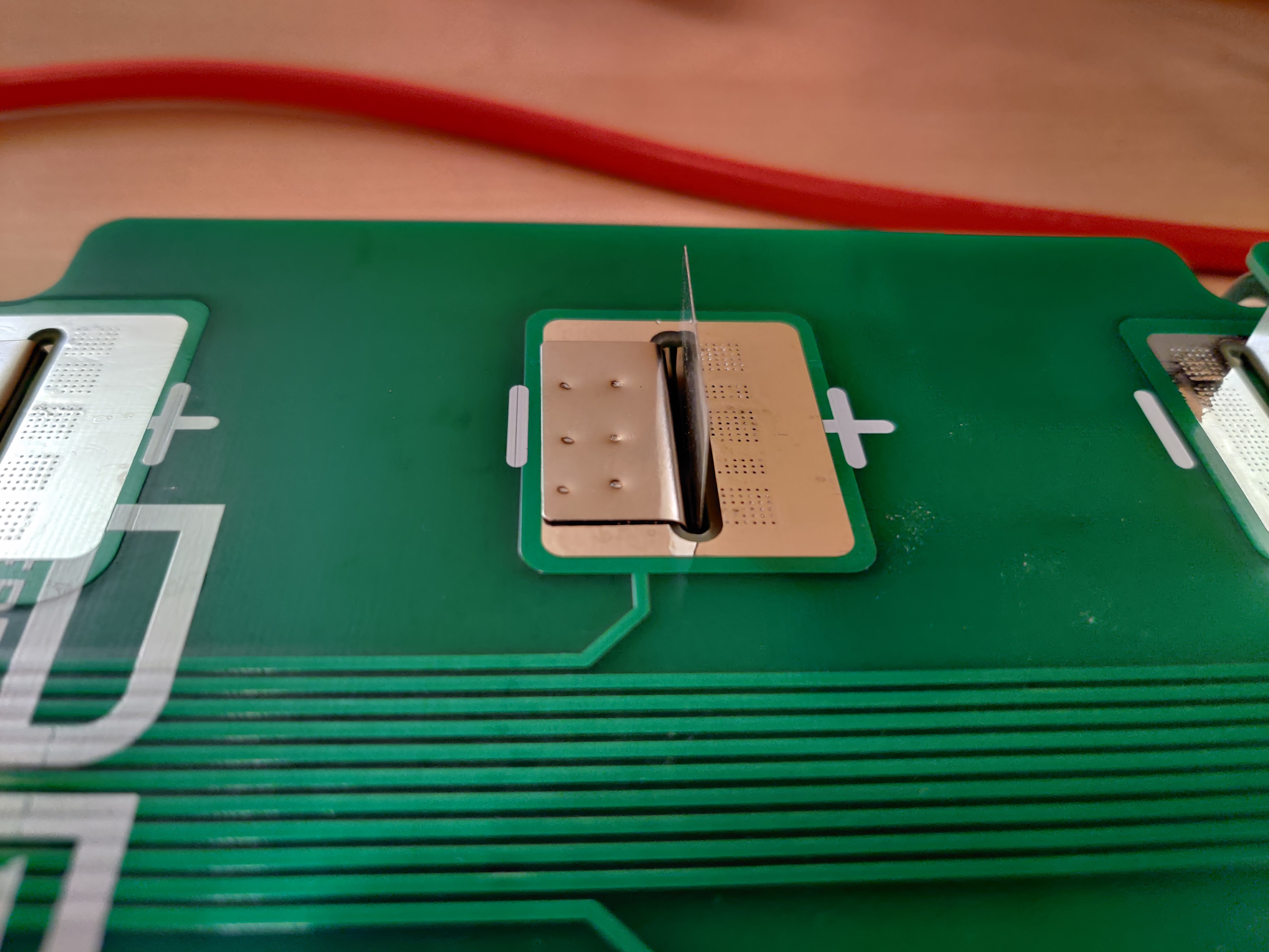
For the single-slit connections, fold the first nickel tab down, spot weld it in place. (You are going to smell the PCB, thats normal and probably fine. As with any welding or soldering, do this in a well ventilated space.) Then fold down the second tab right on top of it and weld it down.
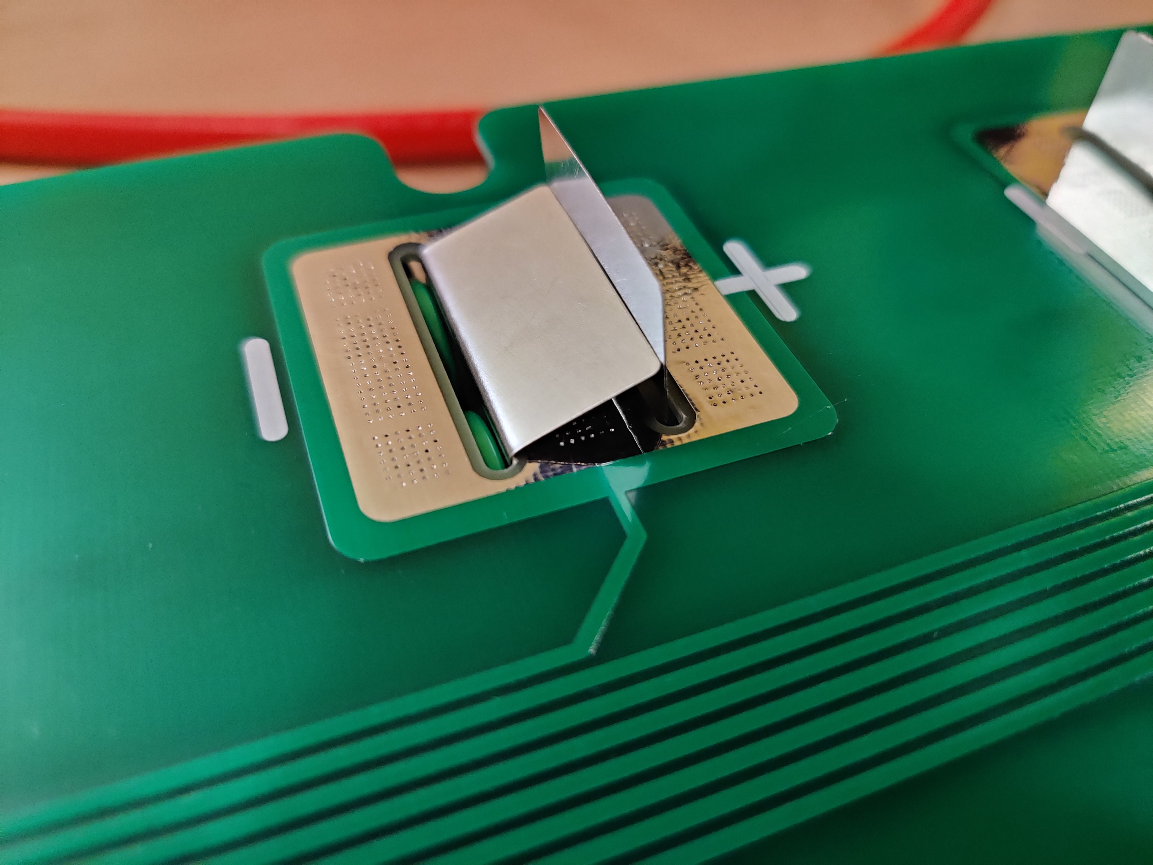
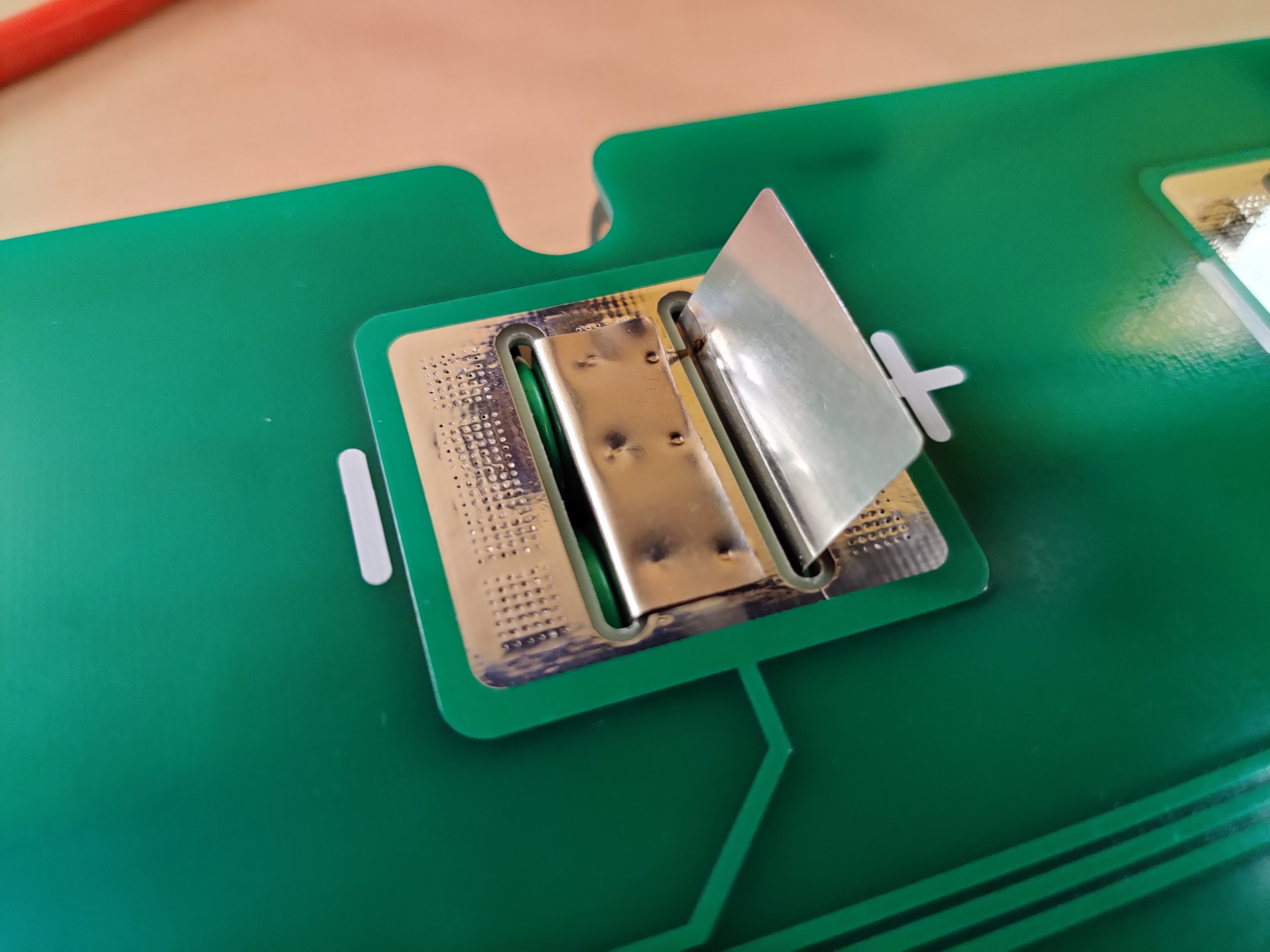
For the double-slit connections, you have two options. The first option is to fold each tab away from each other, and then bridge the gap between them with other nickel or soldered wires or something. Thats dumb though, so dont do it.
The better option is to fold them in towards each other and weld them together just like the single-slit connections. Whichever tab you fold down first is going to be a little too long, so trim 2 or 3 millimeters off it and then weld. Then fold the next down and weld.
When you get to the packs on the end, there is no slit. The tab just folds over the end of the board.
Step 5: Beef up them series connections 💪
As I mentioned, you will want more than just your nickel tabs and copper pour on the PCB carrying the series current. The simplest way to do this is just flood each joint with solder.
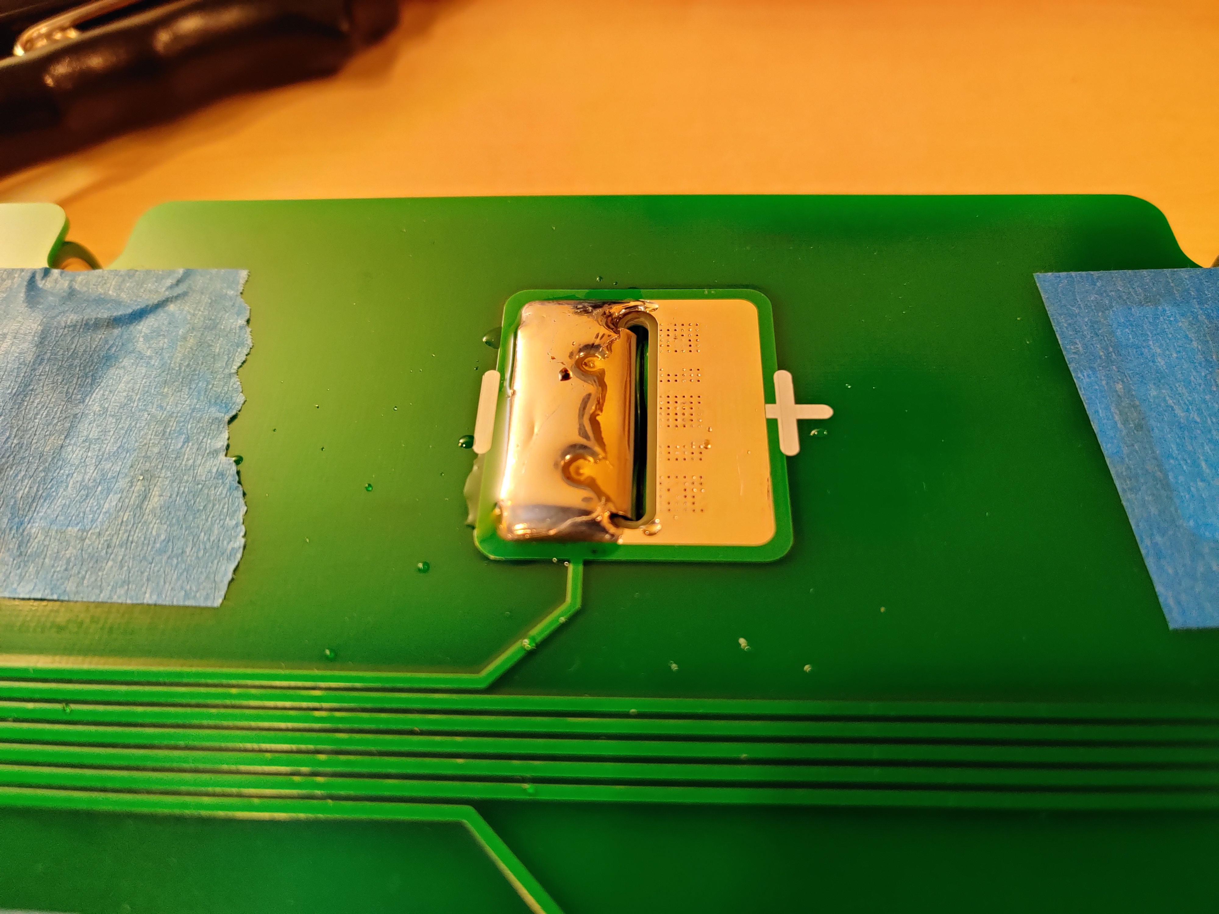
You are going to want a big hot iron for this so you can melt a lot of solder really quick. While we are not soldering straight to the cells, the nickel tabs will conduct the heat back to the cells if you dont work quick enough. I used a 260w Weller soldering gun and thick rosin core solder. Use what works for you.
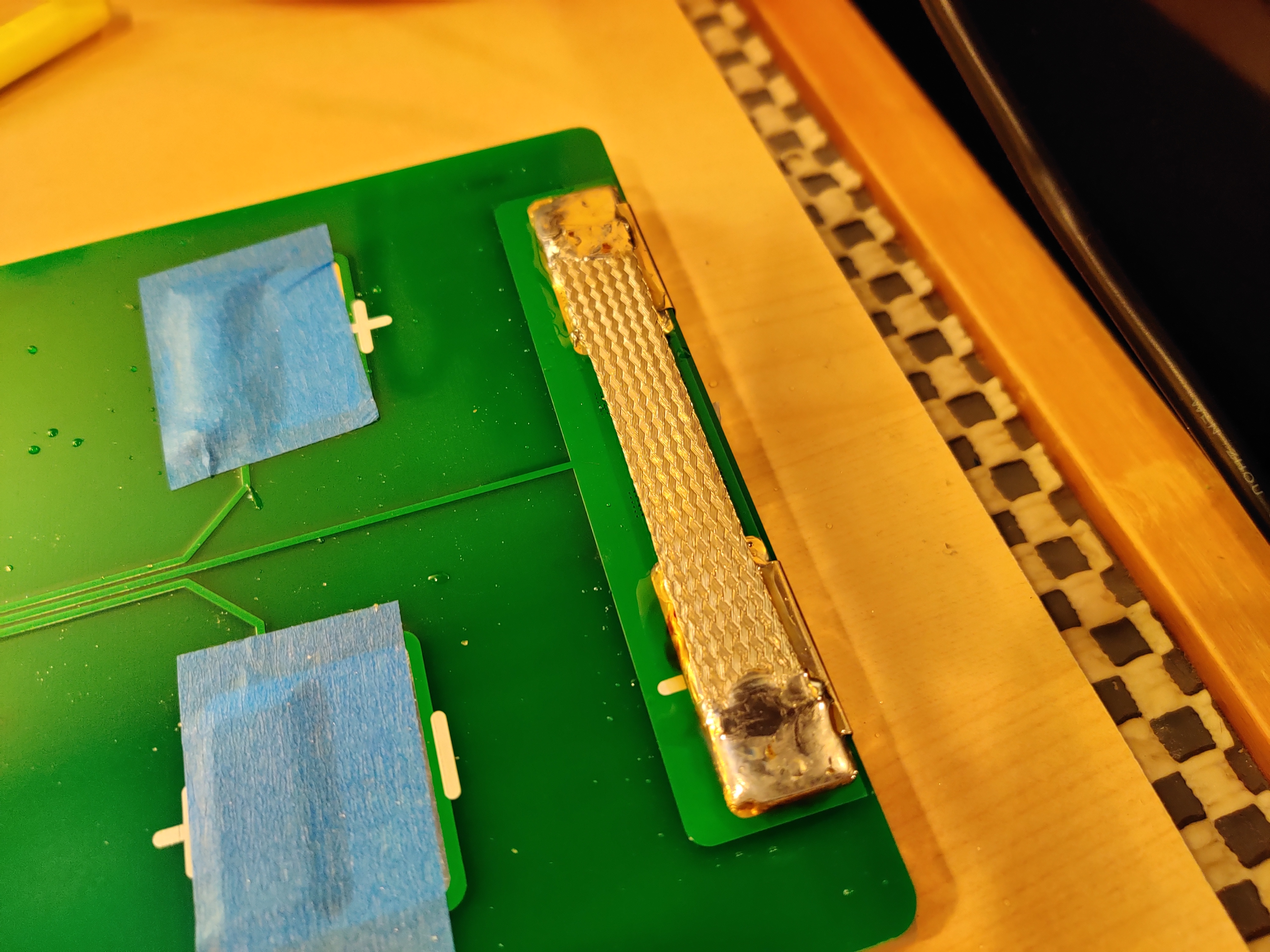
When you get to the ass end of the PCB, you are going have to add something bridging the two terminals. You can spot weld on more nickel and flood each end with solder, solder on some silicone wire, or choose the best option and use some flat copper braid. Flood both pads with solder, and then press the braid into the pool of molten solder while adding more on top. Work quick so the solder doesnt wick too far, and you will be golden. Beware of cold solder joints.
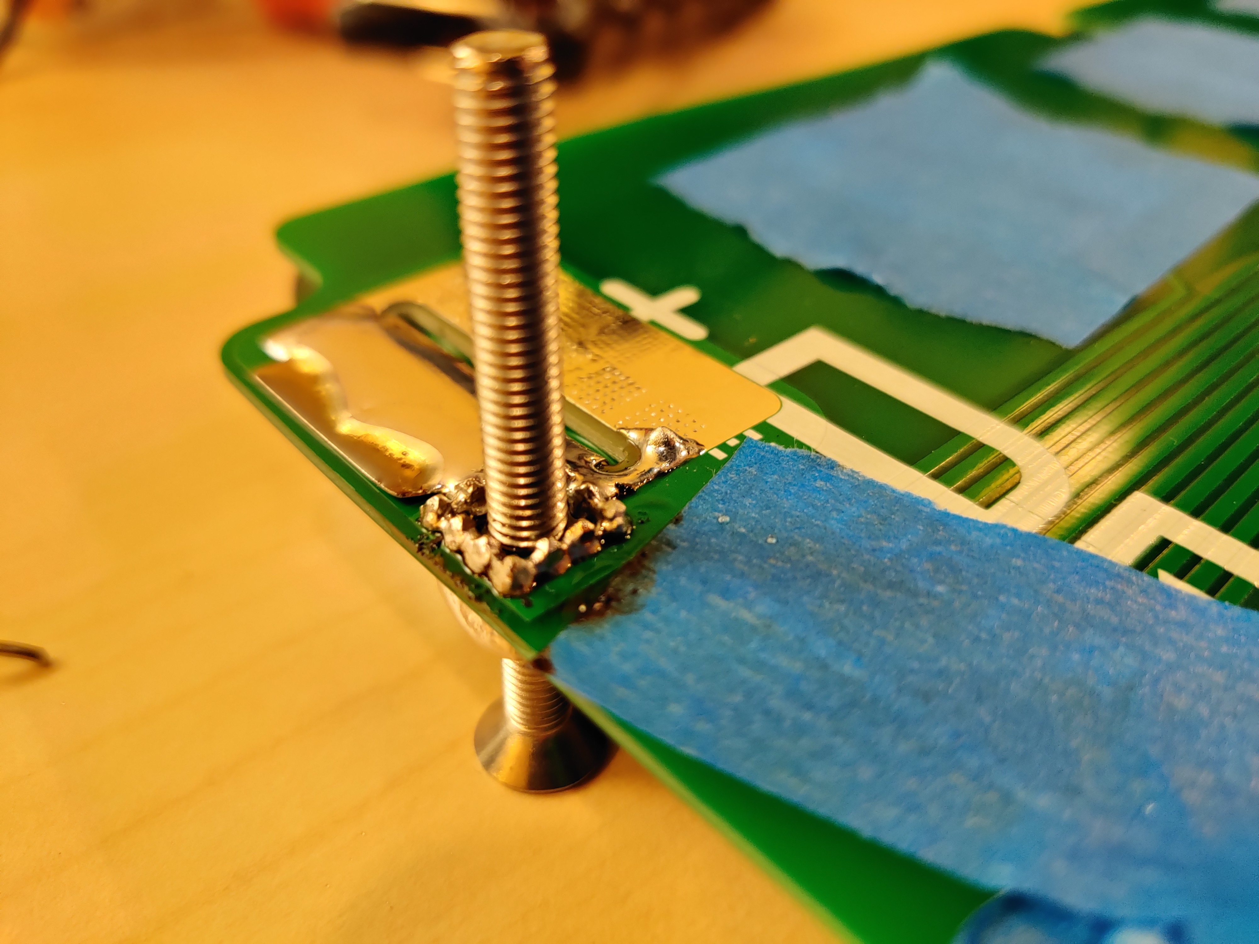
On the terminal end of the PCB you also have to solder in the bush terminals. I found it was easiest to use a long m5 bolt as a standoff against your table to hold the terminal into place while you solder. This also keeps you from accidentally filling the threads with solder lol. Same story, flood the pad with solder.
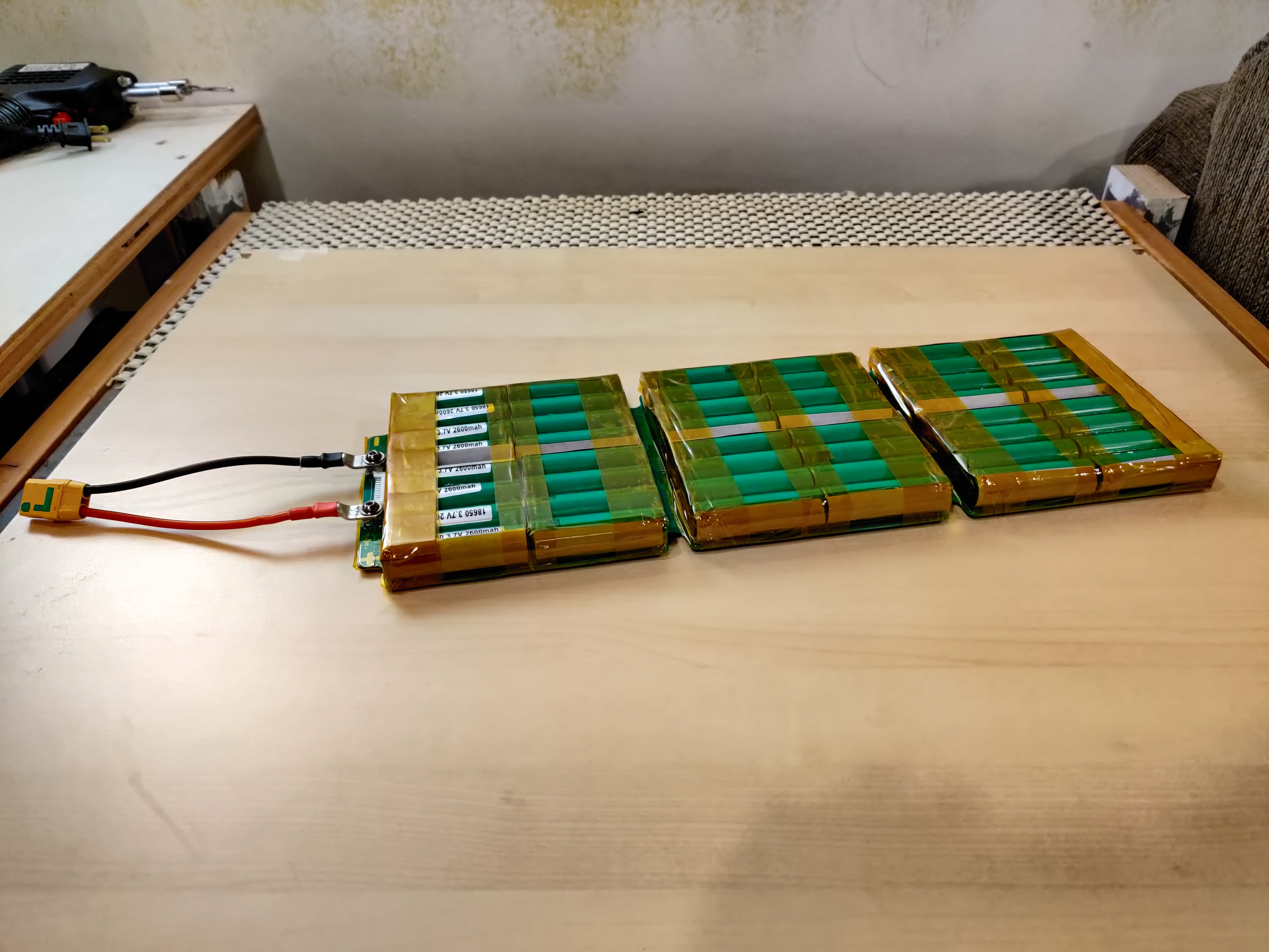
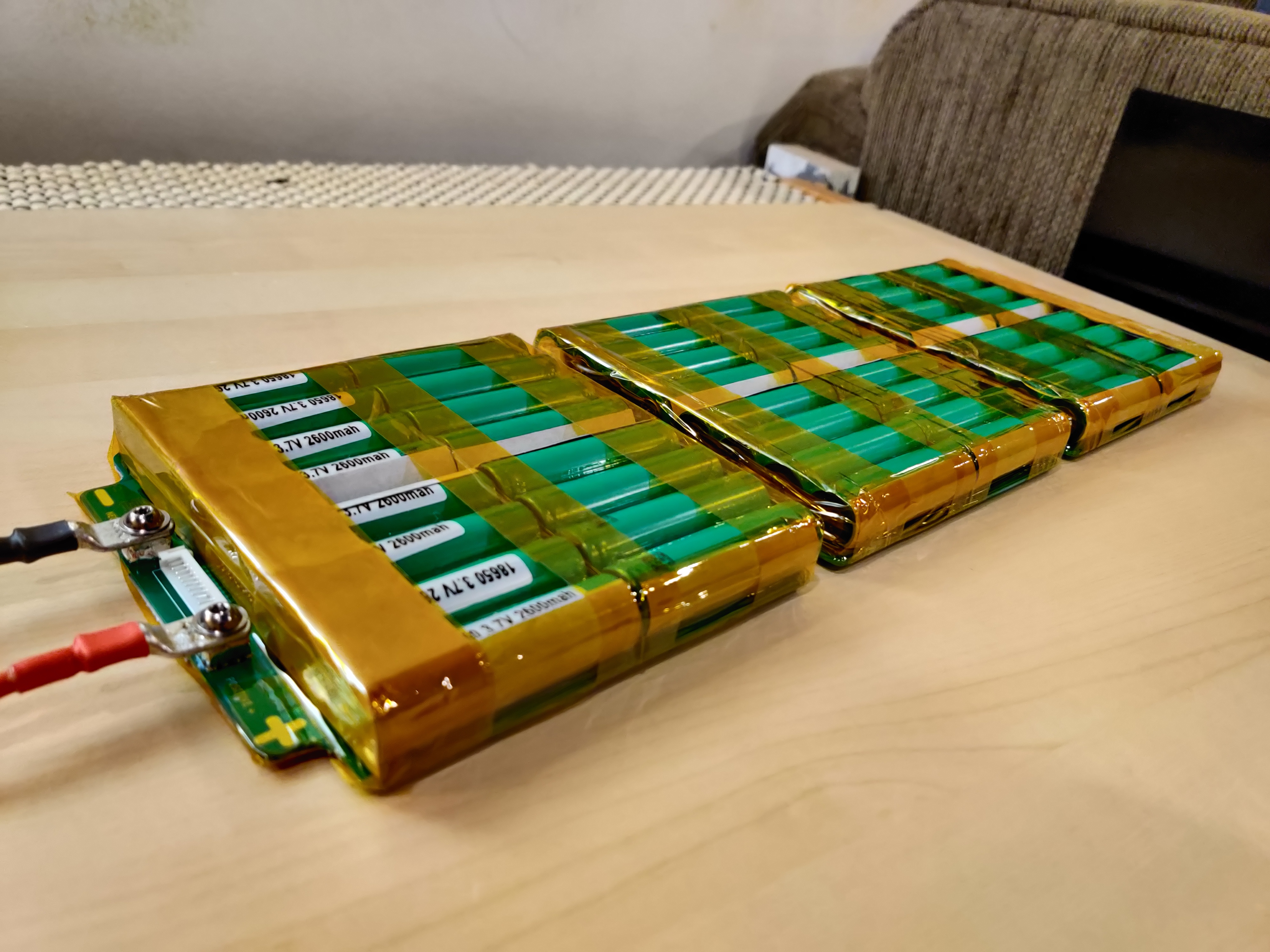
Step 6: Insulate 🧻
Ok, home stretch. Can you feel the amps yet? Can you taste the watt hours? Getting tingly? Good, now stop licking the battery leads and get back to work. This is the easy part.
Fish paper the terminals.
And each end. On the ass end, make sure you use a large enough piece of fish paper for it to fully wrap around all 3 sides.
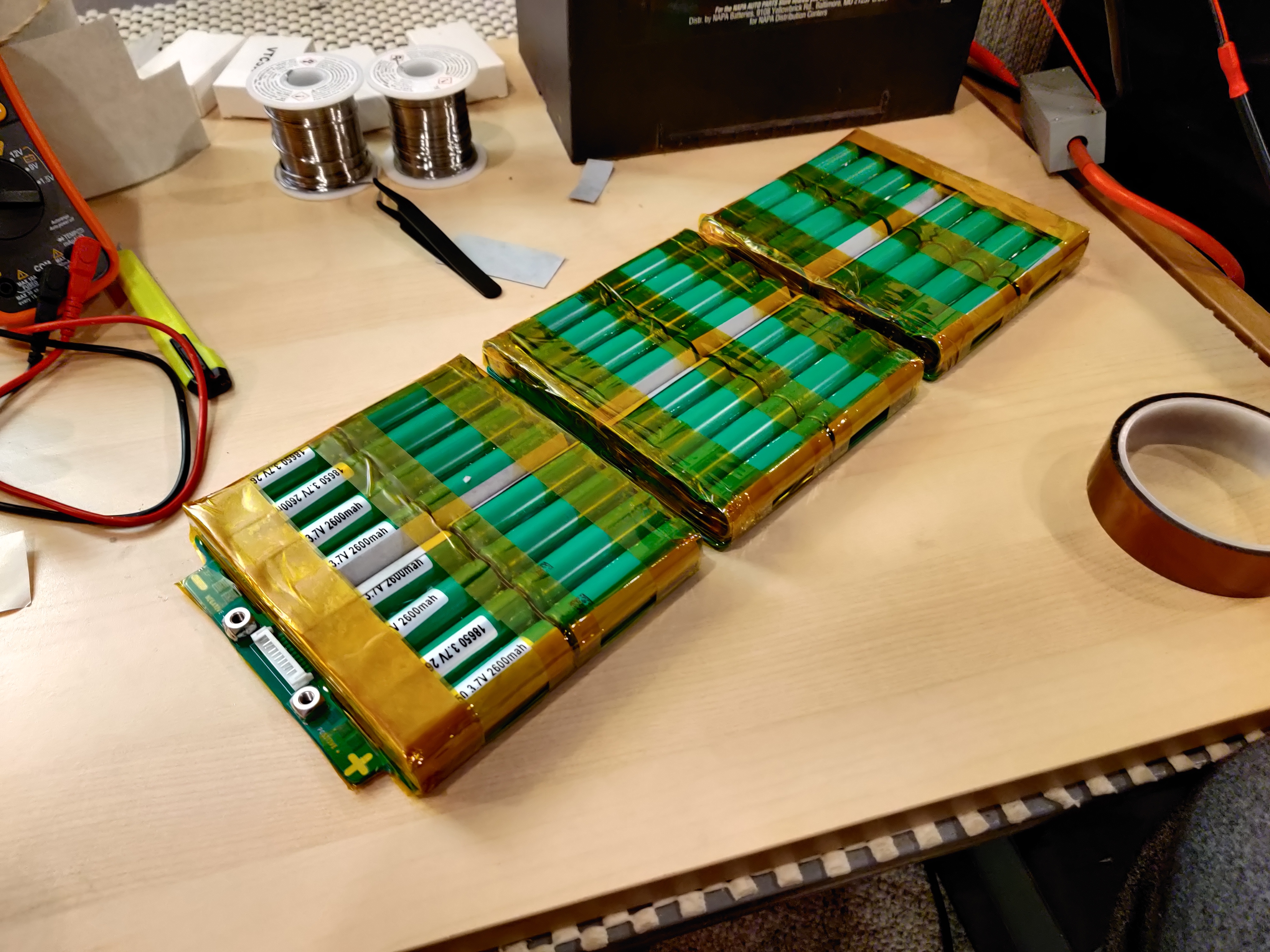
Kapton tape. I did one wrap horizontally around each of the 3 sections, and then banded around that. Line up your bands such that they also hold down your fish paper on the terminals.
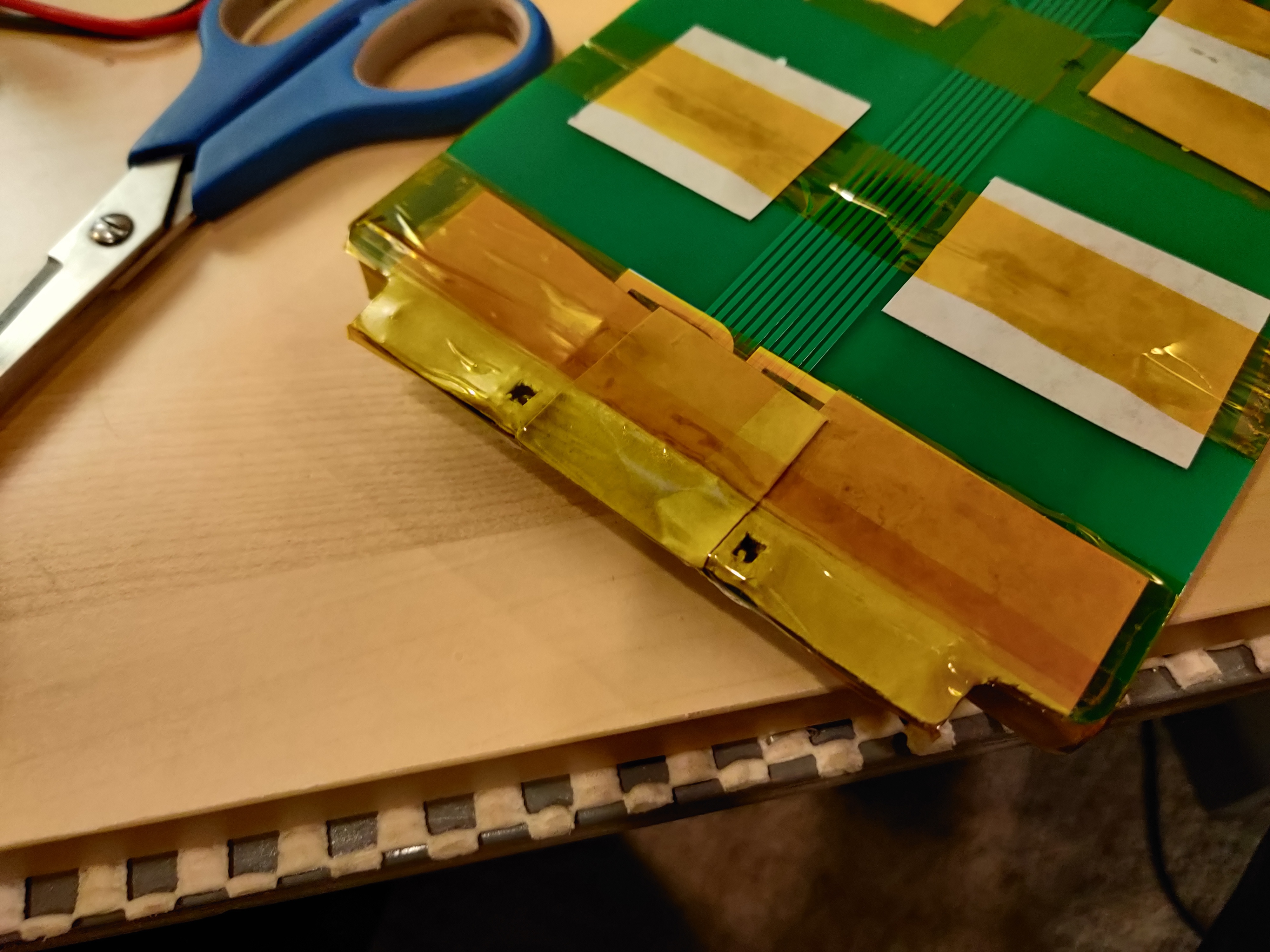
Since you did all the steps in proper order and definitely did not forget to solder the balance plug on until just now, I’m sure you already fish papered the through-hole pins of the plug. Go ahead and kapton tape that whole end as well.
Step 7: Battery leads 🔋
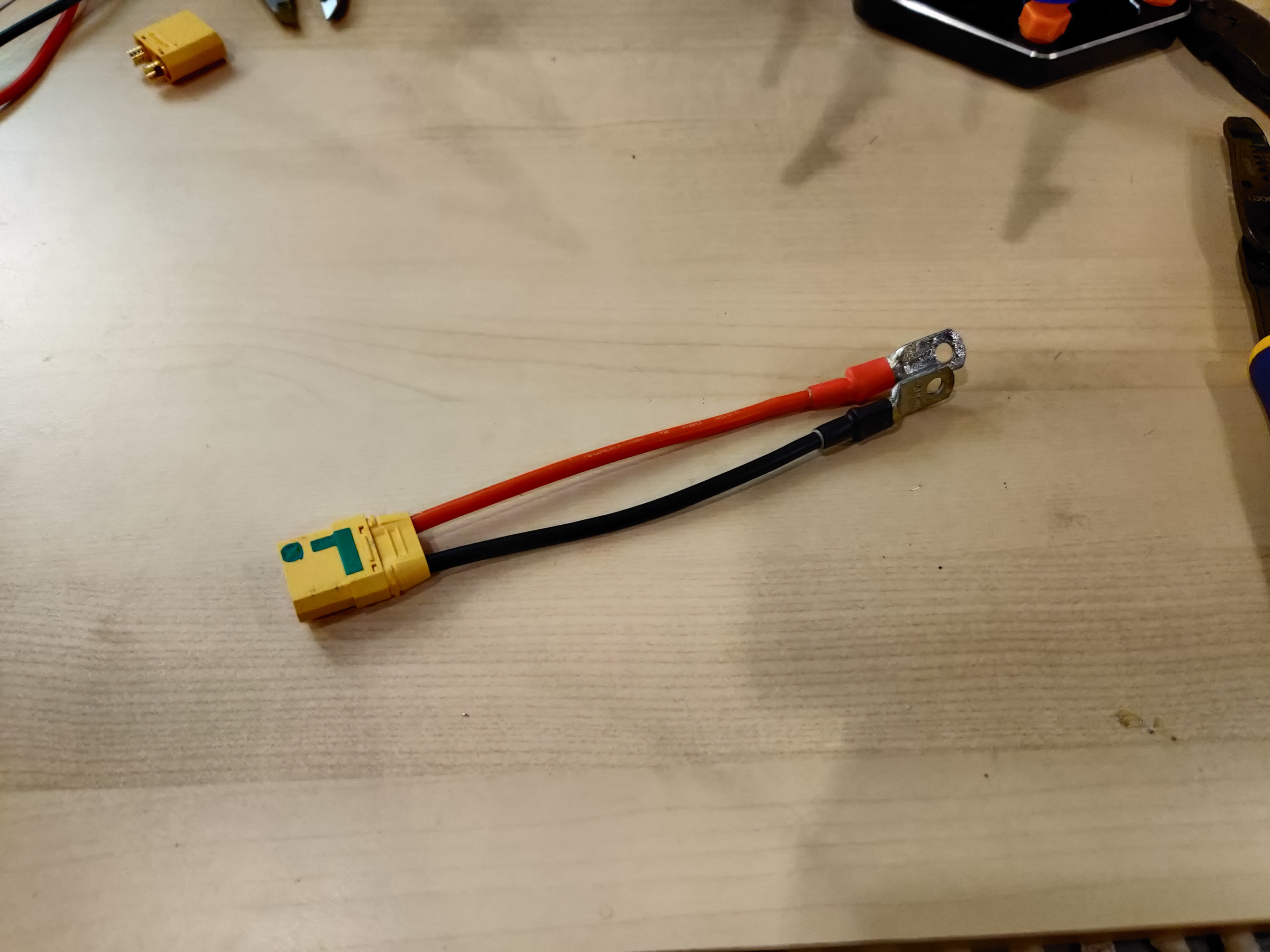
Crimp the lugs onto your wire, and then flood it with solder. If you dont have crimpers, shame on you. Just flood it with solder like a normie then. Use whatever plug you want, but I’m a firm believer that battery leads should always be female XT90S for the anti-spark properties. Bolt it on with your m5x10mm bolts (should be the perfect length to not stick out the back of the bush terminals) and you are ready to rock!
(Should probably also throw some more insulation of some kind over the main battery lugs. And throw some 180mm flat diameter heat shrink on when it shows up from Amazon. Do as I say, not as I do.)
Step 8: Glamour shots! 📸
This step is the most important. Snap some pics of your beautiful build and post them here. Feel free to let us know what cells you are using, as well as any issues you ran into or tips and tricks you picked up along the way!
Order up!